Method for controlling hollow guide blade upper edge plate cavity wall thickness
A technology of hollow guide and cavity wall, which is applied in the direction of mold, core, mold composition, etc., can solve the problems of high production cost, uneven wall thickness, low product qualification rate, etc., to avoid out-of-tolerance and scrap, The effect of improving the qualified rate of products and ensuring the uniformity of wall thickness
- Summary
- Abstract
- Description
- Claims
- Application Information
AI Technical Summary
Problems solved by technology
Method used
Image

Examples
Embodiment 1
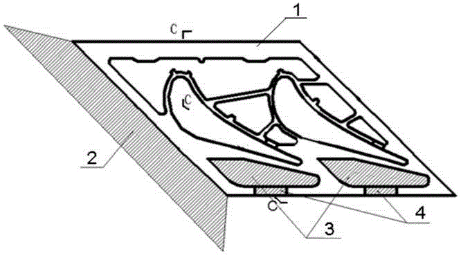
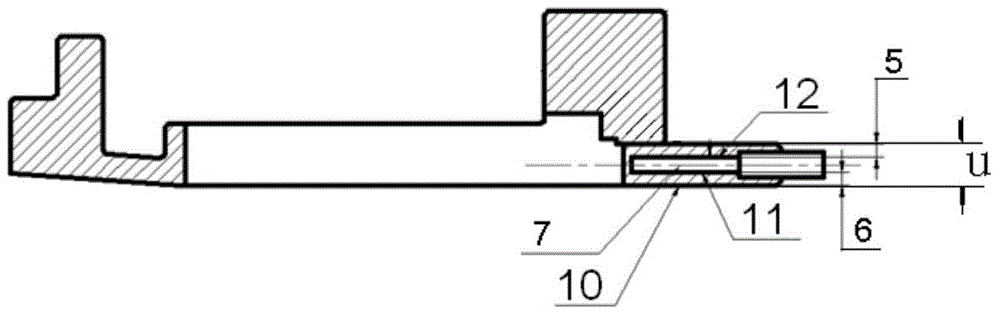
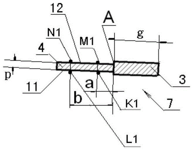
[0035] see Figure 1 to Figure 5 , the method for controlling the cavity wall thickness of the upper edge plate of the hollow guide vane, the cavity refers to the cavity formed by the ceramic core 7 inside the trailing edge of the upper edge plate 1 of the hollow guide vane, and the wall thickness of the cavity refers to The upper wall thickness of the cavity is 5 and the lower wall thickness of the cavity is 6; it is characterized in that the wall thickness of the casting cavity is controlled by changing the wall thickness of the wax model cavity of the upper edge plate of the hollow guide vane, and the ceramic core 7 core body 3 The leading edge of the core is tilted toward the non-runner surface, so that the angle between the lower surface 11 of the core body 3 and the wax mold runner surface 10 of the upper edge plate of the hollow guide vane is α=0°30′, and the specific steps are as follows:
[0036] 1. Determine the position of the central point of the waxy core support ...
Embodiment 2
[0047] see Figure 1 to Figure 5 , the method for controlling the cavity wall thickness of the upper edge plate of the hollow guide vane, the cavity refers to the cavity formed by the ceramic core 7 inside the trailing edge of the upper edge plate 1 of the hollow guide vane, and the wall thickness of the cavity refers to The upper wall thickness of the cavity is 5 and the lower wall thickness of the cavity is 6; it is characterized in that the wall thickness of the casting cavity is controlled by changing the wall thickness of the wax model cavity of the upper edge plate of the hollow guide vane, and the ceramic core 7 core body 3 The leading edge of the core is tilted toward the non-runner surface, so that the angle α between the lower surface 11 of the core body 3 and the wax mold runner surface 10 of the upper edge plate of the hollow guide vane is α = 0°45′, and the specific steps are as follows:
[0048] 1. Determine the position of the central point of the waxy core supp...
Embodiment 3
[0059] see Figure 1 to Figure 5 , the method for controlling the cavity wall thickness of the upper edge plate of the hollow guide vane, the cavity refers to the cavity formed by the ceramic core 7 inside the trailing edge of the upper edge plate 1 of the hollow guide vane, and the wall thickness of the cavity refers to The upper wall thickness of the cavity is 5 and the lower wall thickness of the cavity is 6; it is characterized in that the wall thickness of the casting cavity is controlled by changing the wall thickness of the wax model cavity of the upper edge plate of the hollow guide vane, and the ceramic core 7 core body 3 The leading edge of the core is tilted toward the non-runner surface, so that the angle α between the lower surface 11 of the core body 3 and the wax mold runner surface 10 of the upper edge plate of the hollow guide vane is α = 1°, and the specific steps are as follows:
[0060] 1. Determine the position of the central point of the waxy core support...
PUM
| Property | Measurement | Unit |
|---|---|---|
| diameter | aaaaa | aaaaa |
| width | aaaaa | aaaaa |
| thickness | aaaaa | aaaaa |
Abstract
Description
Claims
Application Information
 - R&D
- Intellectual Property
- Life Sciences
- Materials
- Tech Scout
- Unparalleled Data Quality
- Higher Quality Content
- 60% Fewer Hallucinations
Browse by: Latest US Patents, China's latest patents, Technical Efficacy Thesaurus, Application Domain, Technology Topic, Popular Technical Reports.
© 2025 PatSnap. All rights reserved.Legal|Privacy policy|Modern Slavery Act Transparency Statement|Sitemap|About US| Contact US: help@patsnap.com