
Machine-clamped center drill

A machine clamp and drill bit technology, applied in the direction of center drilling, repair drilling, drilling tool accessories, etc., can solve the problems of easy burning and cutting edge burning, achieve long service life, overcome easy burning, and improve economic benefits Effect

Inactive Publication Date: 2015-09-23
WUJIANG HONGYU MACHINERY
View PDF9 Cites 0 Cited by
  • Summary
  • Abstract
  • Description
  • Claims
  • Application Information

AI Technical Summary

Problems solved by technology

[0003] The present invention proposes an improvement plan for the problem that the cutting edge of the existing center drill is easy to be burned, and adopts the standard short type The drill bit and alloy blade are combined to produce a machine-clip center drill, which overcomes the problem of easy burning of the blade and improves the tool life

Method used


Image

  • Machine-clamped center drill
  • Machine-clamped center drill
  • Machine-clamped center drill

Examples


Embodiment

[0019] Examples: The following specific examples illustrate the implementation of the invention, and those skilled in the art can easily understand other advantages and effects of the present invention from the content disclosed in this specification.

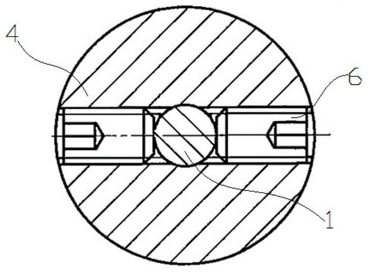
[0020] Such as Figure 1 to Figure 4 As shown, the clamp center drill of the present invention is composed of a center drill bit 1, a blade 2, a blade pressing screw 3, a cutter body 4, a drill adjusting screw 5, and a drill fixing screw 6. The cutter body 4 is a Morse taper rod with a flat tail, which is matched with the inner cone of the tailstock of the machine tool. The diameter of the head is 50mm, and the end face of the head is drilled Reaming, end face symmetrical milling two-axis symmetrical insert pocket 401, threaded hole on the bottom of insert pocket 401; the front end of the center drill bit (1) is a standard short type The twist drill, the back end angle E is 60° conical, The part that exceeds the taper and ...


PUM


Abstract

The invention discloses a machine-clamped center drill. The machine-clamped center drill is composed of a center drill bit, blades, blade pressing screws, a tool body, a drill bit adjustment screw and drill bit fastening screws. The tool body is a Morse taper rod with a flat tail and is matched with the inner cone of a machine tool tailstock, and a reamed hole is drilled in the end face of the head of the tool body; two blade grooves are symmetrically milled in the end faces, and threaded holes are formed in the bottom surfaces of the blade grooves; a standard short twist drill with the diameter being 12 mm is arranged at the front end of the center drill bit, and the rear end of the center drill bit is in the shape of a cone with the taper being 60 degrees; the standard short twist drill with the diameter being 12 mm partially stretches out of the cone shape to be matched with the drill bit adjustment screw so as to be installed on the tool body together with the drill bit adjustment screw through the reamed hole of the tool body, and axial position adjustment and clamping of the center drill bit can be conducted; the two drill bit fastening screws penetrate through the front portion of the tool body to be symmetrically placed so as to clamp the center drill bit in the radial direction; blade positioning grooves are formed in the drill bit with the diameter being 12 mm; the right vertical surfaces of the two blades are tightly attached to the bottom surface, the lower vertical surfaces of the two blades are tightly attached to the drill bit positioning grooves, and the blades are fixed through the blade pressing screws. The machine-clamped center drill solves the problem that burning losses of the blades are caused easily, and the service life of a tool is prolonged.

Description

Technical field: [0001] The invention relates to the technical field of machining tools, in particular to a machine clamp center drill. Background technique: [0002] Such as Figure 5 As shown, for the center holes at both ends of the large-diameter shaft, all manufacturers use high-speed tool steel tapered shank center drilling, the taper shank angle (D) is 60°, the rear end of the tapered shank is connected to the large front end of the cutter body, and the diameter of the large front end Due to quenching and tempering after the rough machining of the axle shaft, the material will harden, the diameter of the cutter body gradually expands during the center drilling process, its linear speed toward the outer periphery increases continuously, and the reaction force of the workpiece on the outer cutting edge gradually increases Large, the cutting edge is easy to burn. Therefore, it is necessary to design a new type of clamp-type center drill that can overcome the shortcoming...

Claims


Application Information

Patent Timeline
Patent Type & Authority Applications(China)
IPC IPC(8): B23B51/08
CPCB23B51/0063B23B51/08
Inventor 王志强
Owner WUJIANG HONGYU MACHINERY
Learn More