Vibrating concrete stirrer

A concrete mixer and mixer technology, applied in the field of machinery, can solve the problems of not meeting the uniformity requirements of concrete, reducing mixing time, reducing mixing costs, etc., and achieve the effects of simple structure, faster mixing speed, and uniform mixing

Inactive Publication Date: 2015-09-23
ZHENGZHOU DENGFENG SMELTING MATERIALS
View PDF0 Cites 12 Cited by
  • Summary
  • Abstract
  • Description
  • Claims
  • Application Information

AI Technical Summary

Problems solved by technology

[0002] Concrete mixers are commonly used equipment in industrial production. It mainly plays the role of mixing or mixing for the preparation of concrete. Concrete mixers are mainly composed of mixing shafts and mixing blades. The efficiency and mixing effect of concrete mixers largely depend on The design of the mixing blade, the reasonable design of the mixing blade can not only improve the uniformity of concrete mixing, but also reduce the mixing time and indirectly reduce the cost of mixing. When the mixer is not in use, a thick layer of concrete will solidify on the inner and outer walls of the concrete mixer, which is not easy to remove

Method used


Image

  • Vibrating concrete stirrer
  • Vibrating concrete stirrer

Examples


Embodiment Construction

[0012] In order to make the objectives, technical solutions and advantages of the present invention clearer, the present invention will be further described in detail below with reference to the accompanying drawings and embodiments. It should be understood that the specific embodiments described herein are only used to explain the present invention, but not to limit the present invention.

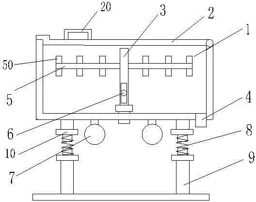
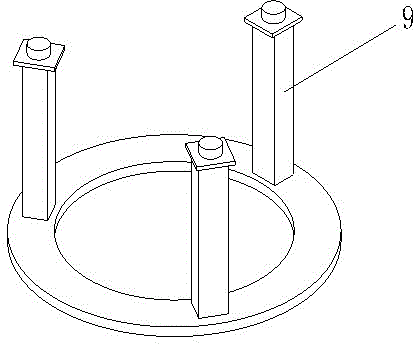
[0013] see figure 1 and figure 2 , figure 1 is a schematic diagram of the structure of the present invention, figure 2 for figure 1 Schematic diagram of the structure of the middle base.

[0014] A vibrating concrete mixer includes a mixer body 1, a main shaft 3, and a support base 9. One end of the main shaft 3 is connected to a motor, and the other end is arranged at the center of the mixer body 1. The upper end of the mixer body 1 is provided with a mixer cover 2. , one end of the blender cover 2 is movably connected with the blender body 1 , and a handle 20 is provided o...


PUM


Abstract

The invention relates to a vibrating concrete stirrer which comprises a stirrer body, a main shaft and a supporting base; one end of the main shaft is connected with an electromotor, and the other end of the main shaft is arranged at the center position of the stirrer body; a stirrer cover is arranged at the upper end of the stirrer body; one end of the stirrer cover is movably connected with the stirrer body; the stirrer body is internally provided with a stirring blade shaft I and a stirring blade shaft II which are connected with the main shaft; the stirring blade shaft I and the stirring blade shaft II are uniformly provided with rectangular stirring blades; a discharge opening is formed in the lower part of the stirrer body, at least two polarizing motors are arranged at the bottom of the stirrer body, and a connecting base on the stirrer body is connected with the supporting base through a spring. The concrete stirrer provided by the invention is simple in structure and reasonable in design, has a degree of freedom in the vertical direction by arranging the polarizing motors, thereby accelerating the stirring speed of concrete. Meanwhile, concretionary concrete on the inner wall body of the stirrer can be further removed.

Description

technical field [0001] The invention relates to the field of machinery, in particular to a vibrating concrete mixer. Background technique [0002] Concrete mixer is used in equipment commonly used in industrial production. It mainly plays the role of mixing or mixing for preparing concrete. Concrete mixer is mainly composed of mixing shaft and mixing blade. The efficiency and mixing effect of concrete mixer are largely determined by The design of the mixing blade, the reasonable design of the mixing blade can not only improve the uniformity of concrete mixing, but also reduce the mixing time and indirectly reduce the mixing cost. When the mixer is not in use, a thick layer of concrete will solidify on the inner surface of the concrete mixer, which is not easy to remove. Therefore, in order to solve the above problems, a new technical solution is provided. SUMMARY OF THE INVENTION [0003] The purpose of the present invention is to provide a vibrating concrete mixer i...

Claims


Application Information

Patent Timeline
Patent Type & Authority Applications(China)
IPC IPC(8): B28C5/48
CPCB28C5/485
Inventor 王建亭
Owner ZHENGZHOU DENGFENG SMELTING MATERIALS
Why Eureka
Try Eureka