
Biological fermentation tank

A technology for biological fermenters and fermenters, which is applied in bioreactor/fermenter combinations, specific-purpose bioreactors/fermenters, biomass post-processing, etc., can solve the failure of raw materials, the influence of sampling analysis, and the influence of stirring blades and other problems to achieve the effect of preventing shedding, increasing wear resistance, and increasing speed

Active Publication Date: 2016-08-24
YANCHENG JIANFENG MACHINERY
View PDF4 Cites 12 Cited by
  • Summary
  • Abstract
  • Description
  • Claims
  • Application Information

AI Technical Summary

Problems solved by technology

Fermentation tanks are widely used in the fermentation of microbial strains. They have the advantages of fast fermentation, cleanliness, and large-scale production. During the production and processing of fermentation tanks, a certain degree of cleanliness must be ensured to avoid exposure of the inoculation port and sampling port of the fermentation tank to In the air, the fermented products exposed to the air are polluted by various bacteria, viruses, fungi, etc. in the air that are not conducive to the growth and reproduction of bacteria, which will affect the fermentation effect of the fermenter, cause a certain amount of waste, and even affect the sampling analysis. A certain influence makes the raw materials invalid. Therefore, the sealing of the fermenter is the key problem to be solved in the production process of the fermenter.
[0003] The quality of the stirring blades in the fermenter and the shape of the stirring blades have a certain influence on the stirring effect of the fermenter. The existing stirring blades are easily affected by the fermented product, which will cause corrosion and wear to the stirring blades. The stirring material generated during the process will stick to the stirring blade, which will have a certain impact on the stirring blade and reduce the service life of the fermenter

Method used


Image

  • Biological fermentation tank
  • Biological fermentation tank

Examples


Embodiment 1

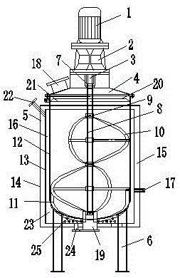
[0031] As can be seen in conjunction with the accompanying drawings, a biological fermenter includes a motor 1, a reducer 2, a stirring device 3, a loam cake 4, a fermenter 5 and a support 6, the lower end of the fermenter 5 is provided with a support 6, and the fermenter 5 The upper end is provided with a loam cake 4, the loam cake 4 is provided with a stirring port 7, the stirring device 3 is arranged in the stirring port 7, the motor 1 is connected with the stirring device 3 through a reducer 2, and the stirring device 3 Comprising a stirring shaft 8 and a stirring blade 9 arranged on the stirring shaft 8, the stirring blade 9 includes a first stirring blade 10 and a second stirring blade 11, and the second stirring blade 11 is arranged at the lower end of the stirring shaft 8, so The first stirring blade 10 is a Jiaolong rotating blade, the second stirring blade 11 is a frame-type stirring blade, the outside of the stirring blade 9 is provided with a coating, and the fermen...

Embodiment 2

[0051] A coating is provided on the outside of the stirring blade 9, and the thickness of the coating is 1 mm.

[0052] The processing technology of the coating is as follows: 1) After cleaning the metal surface of the stirring blade 9 with acetone for 6 minutes, put the stirring blade 9 into the mixture of clear water, acetone and absolute ethanol, and clean the stirring blade 9 Perform ultrasonic treatment for 14 minutes, then put the stirring blade 9 into the distilled aqueous solution to clean the stirring blade 9 for 8 minutes; the weight ratio of the clear water, acetone and absolute ethanol is 3:5:3;

[0053] 2) Add 50 parts of deionized water to 38 parts of polyethylene and stir continuously, and add 5 parts of crosslinking agent during the stirring process and stir for 30 minutes;

[0054] 3) Put 5 parts of shell powder and 8 parts of bone powder into 42% ethanol solution, stir for 10 minutes, then filter, put the filtered mixture into a 0.8MPa high-pressure separator...

Embodiment 3

[0064] A coating is provided on the outside of the stirring blade 9, and the thickness of the coating is 1.2 mm.

[0065] The processing technology of the coating is as follows: 1) After cleaning the metal surface of the stirring blade 9 with acetone for 6 minutes, put the stirring blade 9 into the mixture of clear water, acetone and absolute ethanol, and clean the stirring blade 9 Perform ultrasonic treatment for 16 minutes, then put the stirring blade 9 into the distilled aqueous solution to clean the stirring blade 9 for 7 minutes; the weight ratio of the clear water, acetone and absolute ethanol is 3:5:3;

[0066] 2) Add 48 parts of deionized water to 41 parts of polyethylene and stir continuously, and add 8 parts of crosslinking agent during the stirring process and stir for 29 minutes;

[0067] 3) Put 6 parts of shell powder and 7 parts of bone powder into 42% ethanol solution, stir for 12 minutes, then filter, put the filtered mixture into a 0.8MPa high-pressure separat...


PUM

PropertyMeasurementUnit
thicknessaaaaaaaaaa
diameteraaaaaaaaaa
thicknessaaaaaaaaaa

Abstract

The invention relates to a biological fermentation tank which comprises a motor, a speed reducer, a stirring device, an upper cover, a fermentation bucket and a support. The upper cover is arranged at the upper end of the fermentation bucket and provided with a stirring opening, and the stirring device is arranged in the stirring opening and comprises a stirring shaft and stirring blades arranged on the stirring shaft. The stirring blades comprise the first stirring blade and the second stirring blade, the second stirring blade is arranged at the lower end of the stirring shaft, the first stirring blade is a flood dragon rotary blade, and the second stirring blade is a frame type stirring blade. Coatings are arranged on the outer sides of the stirring blades, the fermentation bucket is provided with an inner barrel body, an outer jacket and a shell in sequence from inside to outside, a heat preservation device is arranged between the outer jacket and the shell, a heating device is arranged between the inner barrel body and the outer jacket, and a sensor is arranged in the heat preservation device. The stirring blades are formed by combining the flood dragon rotary blade and the frame type stirring blade, therefore, reactants can be comprehensively stirred and can be effectively prevented from being pasted to the inner wall of the fermentation bucket, and the reaction rate is increased.

Description

technical field [0001] The invention relates to the field of reaction vessels, in particular to a biological fermentation tank. Background technique [0002] The biological fermentation tank is an external environment device for microorganisms to produce, reproduce and form products during the fermentation process. Compared with traditional containers, it can strictly sterilize the production process of the fermentation tank, and timely feed the fermented products. Stirring, during the production process, it is necessary to automatically control the temperature, pressure, and air flow and provide a good fermentation environment. Fermentation tanks are widely used in the fermentation of microbial strains. They have the advantages of fast fermentation, cleanliness, and large-scale production. During the production and processing of fermentation tanks, a certain degree of cleanliness must be ensured to avoid exposure of the inoculation port and sampling port of the fermentation...

Claims


Application Information

Patent Timeline
Patent Type & Authority Applications(China)
IPC IPC(8): C12M1/34C12M1/02C12M1/00
CPCC12M23/20C12M23/38C12M23/48C12M27/08C12M41/12C12M41/18C12M41/24
Inventor 郑祥兵
Owner YANCHENG JIANFENG MACHINERY
Learn More