Combined type ceiling hanging part and wood veneer ceiling installing process

An installation process and technology of decorative panels, applied in the direction of ceilings, building components, walls, etc.

Active Publication Date: 2015-09-23
江苏巨星铭创幕墙新材料有限公司
View PDF10 Cites 17 Cited by
  • Summary
  • Abstract
  • Description
  • Claims
  • Application Information

AI Technical Summary

Problems solved by technology

[0004] The technical problem to be solved by the present invention is a new type of adjustable stone combined ceiling hanger. The combined ceiling hanger provided by the invention can make the use of the stone suspended ceiling more firm and safe, and the design stre

Method used


Image

  • Combined type ceiling hanging part and wood veneer ceiling installing process
  • Combined type ceiling hanging part and wood veneer ceiling installing process
  • Combined type ceiling hanging part and wood veneer ceiling installing process

Examples


Embodiment 1

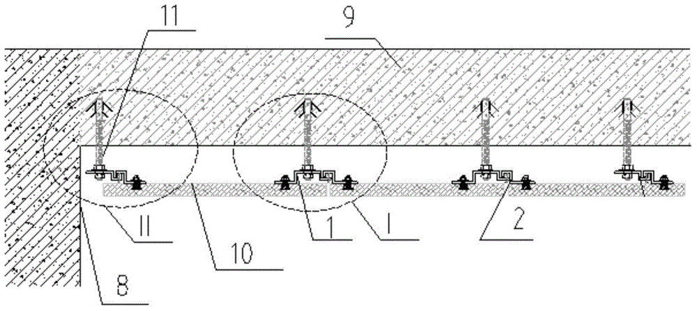
[0037] Such as figure 1 , 6 , 7, the left end of the upper horizontal portion of the Z-shaped hook 1 extends downwards with a joint 3.

[0038] Such as figure 1 , 7 As shown, the first connector 16 includes an L-shaped hook 14, the upper end of the vertical part of the L-shaped hook 14 extends to the left with a horizontal hanging part 5, and a hanging hole is provided on the horizontal hanging part 5. The horizontal portion of the L-shaped hook 14 extends upwards with a second joint 7, and an adjusting screw 4 is installed on the horizontal portion of the L-shaped hook 14.

[0039] Such as figure 1 , 6 shown, the second connector includes shaped hook 1, The top of the shaped hook 1 is provided with a hanging hole, Adjusting screw rod 4 is installed on the right side horizontal part of shaped hook 1.

[0040] In this embodiment, 2 first connectors and 2 second connectors are used, where the second connector is used at the junction of two stones, and the first conne...

Embodiment 2

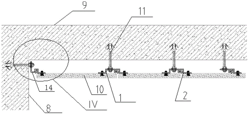
[0043] Such as figure 2 , 9 As shown, 2 first connectors and 2 second connectors are used, wherein the second connector is used at the junction of two stones, and the first connector is used at the beginning or end of the suspended ceiling. Hanging hole is offered on the vertical portion of the 1st L-shaped hitch 14, and the right end of the horizontal portion of the L-shaped hitch 14 extends upwards with a joint 2 7; Adjusting screw rod 4 is positioned at the vertical portion of the Z-shaped hitch 2 Between the joint 1 and 3.

[0044] The construction method of this embodiment is basically the same as that of Embodiment 1, except that the L-shaped hook 14 is installed on the vertical wall 8 because no keel is provided.

Embodiment 3

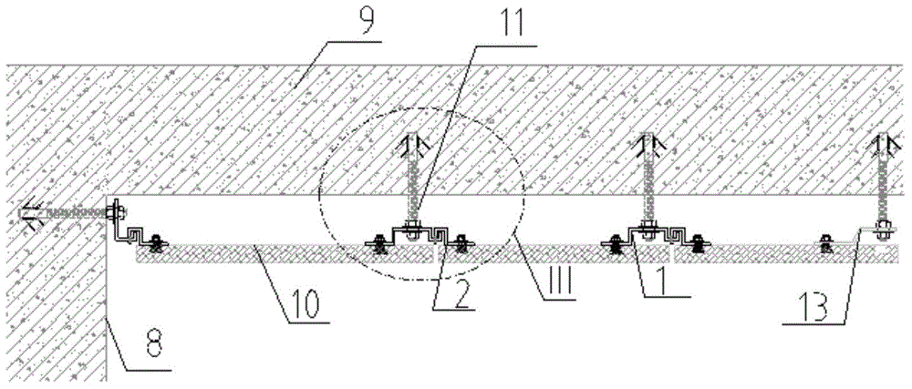
[0046] Such as image 3 , 8 As shown, this embodiment uses one L-shaped hook, two second connectors, and one Z-shaped piece 13 . The right end of the horizontal part of the L-shaped hook extends upwards with a hook joint 2 7 . The right end of the right horizontal portion of the shaped hook 1 extends upwards with a hook joint 3 6 .

[0047] The construction method of this embodiment is basically the same as that of Embodiment 1, the difference is that due to the L-shaped hook, Shaped hooks are all provided with hanging joints, after hooking, hanging joints two and three are located between the vertical part of the Z-shaped hanging piece and the first joint, and the second joint and the third joint have played a role in preventing Z. At this time, it is not necessary to adjust the screw to prevent the sliding of the Z-shaped hook. The upper end of the adjustment screw 4 is in contact with the bottom ends of the second joint and the third joint. When it is necessary to adju...


PUM


Abstract

The invention provides a combined type ceiling hanging part. The combined type ceiling hanging part comprises first connecting parts used for hanging wood veneer to the edge of a ceiling, and second connecting parts used for connecting two adjacent sheets of wood veneer. The first connecting parts are Z-shaped parts or L-shaped hanging part bodies, and the second connecting parts comprise Z-shaped hanging part bodies. Z-shaped hanging part bodies are hung to the horizontal edges of the L-shaped hanging part bodies and the horizontal edges of the right sides of the Z-shaped hanging part bodies. The left ends of the horizontal parts of the upper ends of the Z-shaped hanging part bodies extend downwards to form hanging heads. Adjusting screw rods are installed on the horizontal edges of the L-shaped hanging part bodies and the horizontal edges of the right sides of the Z-shaped hanging part bodies and located between the vertical portions of the Z-shaped hanging part bodies and the hanging heads. The combined type ceiling hanging part is wide in application range, can be used for point hanging and nail hanging, and can be applied to a traditional T-type hanging system. By means of the combined type ceiling hanging part, the stone ceiling is firmer and safer to use, stress points are designed reasonably, the height of four corners of a stone can be adjusted conveniently, and the combined type ceiling hanging part is simple in structure, capable of being assembled and disassembled independently and high in operability, and saves labor and cost while improving the safety.

Description

technical field [0001] The invention belongs to the field of building ceiling design and construction, and in particular relates to a combined ceiling pendant suitable for stone ceilings and a ceiling installation process. Background technique [0002] In the existing building curtain wall technology, the stone curtain wall is composed of a structural support, a panel and a pendant system, and the pendant system is a connector for attaching the panel to the structural support. Common pendant systems include T type, back bolt type and small unit type. The T type is easy to connect, low in cost, and widely used. The utility model patent with the application number 201220077278.5 provides a small unit stone ceiling pendant system with double safety structure. The system is installed on the beam and consists of several sets of identical components. One end of the main hanger is fixed on the side surface of the beam, and the other end is a hook structure. One end of the sub-han...

Claims


Application Information

Patent Timeline
IPC IPC(8): E04B9/18E04B9/22E04B2/88E04G21/14
Inventor 李诗全
Owner 江苏巨星铭创幕墙新材料有限公司
Why Eureka
Try Eureka