
Compression ring lock for torque transmission devices and clutch devices or clutches

A technology of a torque transmission device and a clutch device, which is applied in the fields of torque transmission devices and pressure ring locking parts, and can solve problems such as installation space requirements

Active Publication Date: 2020-06-16
SCHAEFFLER TECH AG & CO KG
View PDF5 Cites 0 Cited by
  • Summary
  • Abstract
  • Description
  • Claims
  • Application Information

AI Technical Summary

Problems solved by technology

The disadvantage here is that the two components have an axial installation space requirement

Method used


Image

  • Compression ring lock for torque transmission devices and clutch devices or clutches
  • Compression ring lock for torque transmission devices and clutch devices or clutches
  • Compression ring lock for torque transmission devices and clutch devices or clutches

Examples


Embodiment Construction

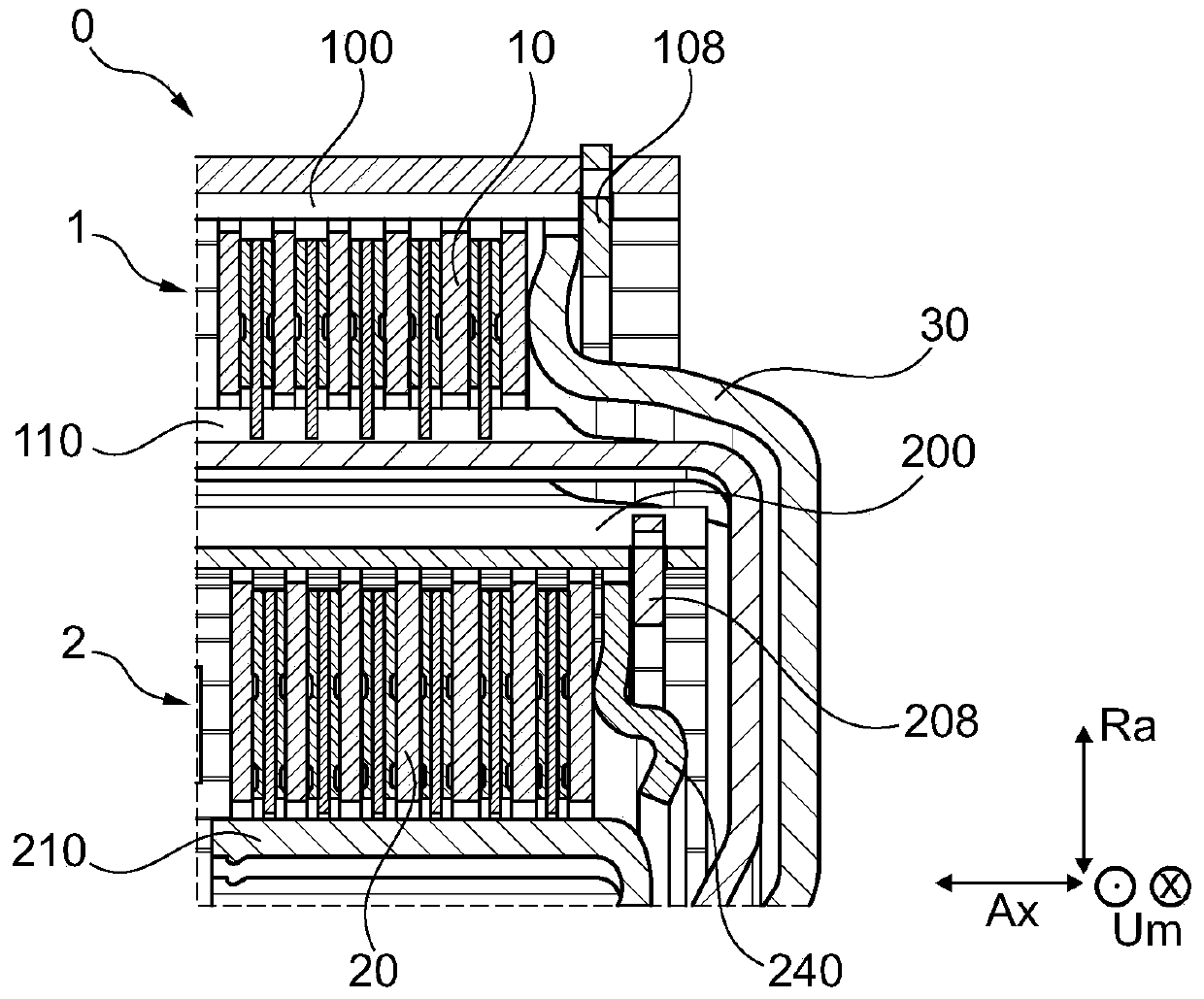
[0024] The following explanation of the invention relates to the axial direction Ax, the axis of rotation Ax, the radial direction Ra and the circumferential direction Um around a torque transmission device 0 of a vehicle, in particular a motor vehicle with a gasoline or diesel engine. These position specifications also relate, for example, to the crankshaft, drive train and transmission of the motor vehicle. exist figure 1 The torque transmission device 0 shown in is configured as a wet-running dual clutch with two clutches 1 , 2 , two clutch devices 1 , 2 or two clutch mounts 1 , 2 . The torque transmission device 0 can also be designed as a partial clutch, as a single clutch or as a multiclutch. Furthermore, the torque transmission device 0 can have a damping device, such as a torsional vibration damper, and / or a vibration damping device, such as a centrifugal pendulum device. The clutches 1 , 2 can be configured as friction plate clutches, single-plate clutches or the li...


PUM


Abstract

The invention relates to a pressure ring lock for a torque transmission device, preferably a clutch device or a clutch, of a drive train of a vehicle, in particular a motor vehicle, wherein the pressure ring lock comprises an assembly area and a lock area, the two Two regions form at least the pressure ring lock, and one region can be supported on the pressure ring of the torque transmission device and the other region can be supported on the friction lining carrier of the torque transmission device. The invention also relates to a clutch arrangement or clutch for a drive train of a vehicle, in particular a motor vehicle, with a disk carrier, a disk pack and a pressure ring, wherein the pressure ring is suspended in the disk carrier in such a way that by means of The pressure ring can actuate the disk pack, wherein the pressure ring is secured against rotation relative to the disk carrier by means of a pressure ring lock.

Description

technical field [0001] The invention relates to a torque transmission device, preferably a clutch device or a pressure ring lock of a clutch, for a drive train of a vehicle, in particular a motor vehicle. The invention also relates to a method for securing a clutch arrangement or a clutch connection, preferably a bayonet lock. Furthermore, the invention relates to a clutch device or a clutch and a torque transmission device, in particular a wet-running double clutch. Background technique [0002] The internal combustion engine of a motor vehicle only makes available power to the driver of the motor vehicle within a defined rotational speed range. In order to be able to use this speed range for different driving states of the motor vehicle, the motor vehicle requires a transmission that can be shifted automatically or manually. This transmission is mechanically coupled to the internal combustion engine via a clutch. A plurality of clutches are used in the drive train of a ...

Claims


Application Information

Patent Timeline
Patent Type & Authority Patents(China)
IPC IPC(8): F16D13/52
CPCF16D13/683F16D13/70F16D2300/12
Inventor J·芬克
Owner SCHAEFFLER TECH AG & CO KG
Learn More