
Measuring instrument positioning device suitable for high-altitude occasions

A technology of measuring instruments and positioning devices, which is applied in the directions of supporting machines, thermal development of materials, mechanical equipment, etc., can solve the problems that the accuracy of test data cannot be guaranteed, and achieve the effects of low cost, simple overall structure and improved reliability.

Active Publication Date: 2015-09-23
SICHUAN UNIV
View PDF8 Cites 5 Cited by
  • Summary
  • Abstract
  • Description
  • Claims
  • Application Information

AI Technical Summary

Problems solved by technology

Among them, when testing the heat transfer coefficient of materials, it is necessary to test the wind speed and temperature of the outer wall. At present, it is difficult to install the wind speed tester to keep the probe at a sufficient distance from the outer wall when testing the wind speed of the outer wall. Generally, the wind speed tester is only bundled. On the edge of the window, this causes the wind speed tested by the anemometer to be only the wind speed of the outer wall boundary layer, rather than the real wind speed blown to the glass and the outer wall, and the accuracy of the test data cannot be guaranteed.

Method used


Image

  • Measuring instrument positioning device suitable for high-altitude occasions
  • Measuring instrument positioning device suitable for high-altitude occasions

Examples


Embodiment 1

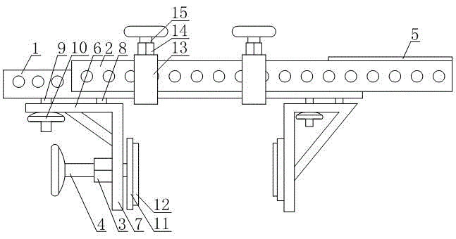
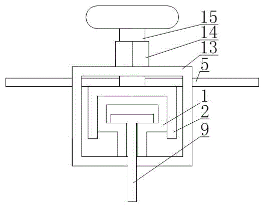
[0021] Such as figure 1 and figure 2 As shown, a measuring instrument positioning device suitable for high-altitude occasions includes a guide rail 1, a grooved mounting rail 2, a positioning plate 11, a positioning bracket and a track locking mechanism, wherein the guide rail 1 of this embodiment is provided with a The opening groove that the positioning bracket matches, the groove body of both the groove-shaped mounting rail 2 and the guide rail 1 of this embodiment open to the same side, the groove-shaped mounting rail 2 is sleeved on the guide rail 1 and is connected to the guide rail by a rail locking mechanism. Rail 1 is firmly connected. In the specific implementation of this embodiment, the track locking mechanism can be realized by bolts passing through the guide rail 1 and the grooved mounting rail 2 and nuts sleeved on the bolts, or screws can be used to connect the guide rail 1 and the grooved mounting rail 2 Lock and fix.

[0022] The positioning bracket of th...

Embodiment 2

[0025] This embodiment makes the following further limitations on the basis of Embodiment 1: in this embodiment, the bracket body of any one of the positioning brackets in the two positioning brackets is connected with a first internal thread column 3, and the first internal thread column 3 is parallel Arranged on the guide rail 1 , this embodiment is also provided with a first threaded adjusting rod 4 passing through the first internally threaded column 3 , and the external thread of the first threaded adjusting rod 4 matches the internal thread of the first internally threaded column 3 . In this embodiment, the positioning disc 11 connected with the positioning bracket of the first internal thread column 3 is specifically connected to the end of the first threaded adjustment rod 4, so that the position of the positioning disc 11 is convenient to be adjusted when the present embodiment is applied. fine-tuning. When this embodiment is applied, the first internal thread column ...

Embodiment 3

[0027]This embodiment makes the following further limitations on the basis of embodiment 1 or embodiment 2: in this embodiment, the side section shape of the groove body of the guide rail 1 is T-shaped, and the positioning guide block 9 is a T-shaped slider. In this way, when the present embodiment is applied, the guide rail 1 can be realized by using standard stainless steel or aluminum alloy profiles with T-shaped grooves, which is convenient for implementation. In order to prevent the positioning bracket from falling off easily when it slides to both ends of the guide rail 1, the opening at one end of the guide rail 1 can be sealed by welding in this embodiment.


PUM


Abstract

The invention discloses a measuring instrument positioning device suitable for high-altitude occasions. The measuring instrument positioning device comprises a guide rail, a groove type mounting rail, positioning plates, a rail locking mechanism and two positioning supports. The groove type mounting rail is connected with the guide rail through the rail locking mechanism in a fastening mode. Each positioning support comprises a support body, a positioning guide block and a fastening rotary knob. One end of each positioning guide block forms a limiting end arranged in the guide rail, the part, arranged outside the guide rail, of each positioning guide block forms an external thread, the threaded section of each positioning guide block penetrates through the corresponding support body, each fastening rotary knob is arranged on the corresponding positioning guide block in a sleeving mode and compresses the corresponding support body to be tightly attached to the guide rail, and the support bodies of the two positioning supports are each connected with one positioning plate. When the measuring instrument positioning device is used for emergently fixing a measuring instrument for tall buildings, high-altitude flight platforms, field scientific investigation and the like, operation is convenient and fast, time and labor are saved, working efficiency can be improved, and testing precision and reliability can be improved when the measuring instrument positioning device is used for positioning a heat transfer coefficient testing instrument for high-rise buildings.

Description

technical field [0001] The invention relates to the field of surveying instrument installation, in particular to a surveying instrument positioning device suitable for high-altitude occasions. Background technique [0002] In order to evaluate the thermal insulation performance of high-rise building curtain wall glass and new building materials, it is an essential item to test the heat transfer coefficient of materials. Among them, when testing the heat transfer coefficient of materials, it is necessary to test the wind speed and temperature of the outer wall. At present, it is difficult to install the wind speed tester to keep the probe at a sufficient distance from the outer wall when testing the wind speed of the outer wall. Generally, the wind speed tester is only bundled. On the edge of the window, this causes the wind speed tested by the anemometer to be only the wind speed of the boundary layer of the outer wall, rather than the real wind speed blown to the glass and ...

Claims


Application Information

Patent Timeline
Patent Type & Authority Applications(China)
IPC IPC(8): F16M13/02G01N25/20
Inventor 王志宇王清远
Owner SICHUAN UNIV
Learn More