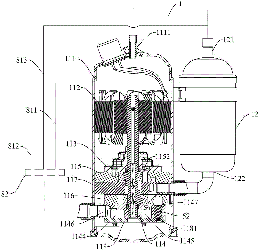
Refrigeration and heating circulating system

A circulating system, refrigeration and heating technology, applied in refrigerators, refrigeration components, refrigeration and liquefaction, etc., can solve the problems of rapid increase in cooling capacity, energy waste, refrigerant overcompression, etc., and achieve the effect of rapid cooling

Active Publication Date: 2015-09-23
GUANGDONG MEIZHI COMPRESSOR +1
View PDF5 Cites 2 Cited by
  • Summary
  • Abstract
  • Description
  • Claims
  • Application Information

AI Technical Summary

Problems solved by technology

[0004] However, in cooling operation under intermediate refrigeration and other working conditions, the pressure ratio is small and the single-stage compression efficiency is improved. If two-stage compression is also used, since two cylinders work at the same time, the friction power will increase faster than the cooling capacity. , at the same time, it may also cause over-compression of the refrigerant, resulting in a reduction in the energy efficiency of the two-stage compression
[0005] Under small load conditions, such as intermediate refrigeration conditions, it is easy to have excess cooling capacity, which leads to energy waste. At the same time, under heavy load conditions, such as ultra-low temperature heating, it is prone to insufficient heating capacity, and the efficiency is very low
Moreover, when the user requires the system to achieve rapid cooling and heating, it is impossible to quickly increase the refrigerant flow

Method used


Image

  • Refrigeration and heating circulating system

Examples


Embodiment Construction

[0025] Embodiments of the present invention are described in detail below, examples of which are shown in the drawings, wherein the same or similar reference numerals designate the same or similar elements or elements having the same or similar functions throughout. The embodiments described below by referring to the figures are exemplary only for explaining the present invention and should not be construed as limiting the present invention.

[0026] In describing the present invention, it should be understood that the terms "center", "transverse", "length", "width", "thickness", "upper", "lower", "front", "rear", " Orientation indicated by Left, Right, Vertical, Horizontal, Top, Bottom, Inner, Outer, Axial, Radial, Circumferential, etc. Or the positional relationship is based on the orientation or positional relationship shown in the drawings, which is only for the convenience of describing the present invention and simplifying the description, and does not indicate or imply ...


PUM


Abstract

The invention discloses a refrigeration and heating circulating system which comprises a liquid accumulator, a compressor, a condenser, an evaporator, a flash vessel, a first throttling device and a second throttling device. When the refrigeration and heating circulating system runs under a small-load working condition, high-pressure refrigerant is pumped into a middle air inlet cavity through an air suction opening, and a control device controls the middle air inlet cavity and a middle air outlet cavity to be communicated. When the refrigeration and heating circulating system stably runs under a large-load and ultralow-temperature heating working condition, medium-pressure refrigerant is pumped into the middle air inlet cavity through the air suction opening, and the control device controls the middle air inlet cavity and the air outlet cavity to be communicated. When the refrigeration and heating circulating system runs under the other large-load working conditions except ultralow-temperature heating, low-pressure refrigerant is pumped into the middle air inlet cavity through the air suction opening, and the control device controls the middle air inlet cavity and the middle air outlet cavity to be separated. The refrigeration and heating circulating system can effectively achieve fast heating and refrigeration.

Description

technical field [0001] The invention relates to the technical field of refrigeration and heating equipment manufacturing, in particular to a refrigeration and heating cycle system. Background technique [0002] It is pointed out in related technologies that due to changes in the external environment and different user demands, the load requirements of the air conditioning system are also different. Moreover, under harsh environmental conditions, users generally require the air conditioning system to be able to achieve rapid cooling and heating. The load of the air-conditioning system varies greatly, and the requirements and performance of the air-conditioning system also vary greatly. [0003] When the load of the air-conditioning system is heavy, such as ultra-low temperature heating, due to the large specific volume of the refrigerant, the air-conditioning system’s compressor suction mass flow rate decreases, which not only leads to a significant reduction in the heating c...

Claims


Application Information

Patent Timeline
Patent Type & Authority Applications(China)
IPC IPC(8): F25B13/00F25B29/00F25B41/06F25B41/00F25B31/00F25B41/30F25B41/40
CPCF25B13/00F25B29/003F25B31/00F25B41/00F25B41/30
Inventor 虞阳波杨国用
Owner GUANGDONG MEIZHI COMPRESSOR
Why Eureka
Try Eureka