Motor rotor intelligent deflection test system

A motor rotor and testing system technology, applied in the direction of motor generator testing, etc., can solve the problems of low measurement accuracy and poor stability, and achieve the effects of high accuracy, good stability, and convenient regulation

Active Publication Date: 2015-09-23
苏州聚博精密设备有限公司
View PDF10 Cites 5 Cited by
  • Summary
  • Abstract
  • Description
  • Claims
  • Application Information

AI Technical Summary

Problems solved by technology

[0003] At present, when the commonly used deflection test system tests the rotating shaft to be tested, the measurement surface is generally a common continuous surface measurement, but the discontinuous surface structure of the fan blade cannot be measured, so the measurement accuracy of the system is low and stable. poor sex

Method used


Image

  • Motor rotor intelligent deflection test system
  • Motor rotor intelligent deflection test system
  • Motor rotor intelligent deflection test system

Examples


Embodiment

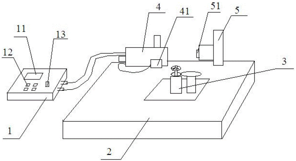
[0023] Such as figure 1 As shown, this embodiment discloses a motor rotor intelligent deflection test system, which includes a control host 1, a test machine 2, a deflection test device installed on the test machine 2, and a component that drives the motor rotor to rotate 3. Fix the motor rotor on the component 3 that drives the motor rotor to rotate, which drives the motor rotor to rotate, and the yaw test device can detect the radial yaw and axial yaw when the motor rotor rotates.

[0024] Specifically, the above-mentioned deflection test device includes: an axial laser displacement meter 4, a displacement sensor-41 that transmits the displacement signal to the above-mentioned axial laser displacement meter 4, a radial laser displacement meter 5, and transmits the displacement signal to The displacement sensor two 51 of the above-mentioned radial laser displacement meter 5, the above-mentioned axial laser displacement meter 4 and the radial laser displacement meter 5 are all...


PUM


Abstract

The invention relates to a motor rotor intelligent deflection test system. The system comprises a testing machine, a deflection test apparatus arranged on the testing machine and an assembly driving a motor stator to rotate. The deflection test apparatus comprises an axial laser displacement meter, a first displacement sensor transmitting displacement signals to the axial laser displacement meter, a radial laser displacement meter, and a second displacement sensor transmitting the displacement signals to the radial laser displacement meter. The axial laser displacement meter and the radial laser displacement meter are arranged on the bench surface of the testing machine, the assembly driving the motor rotor to rotate is arranged below the bench surface of the testing machine, when the assembly driving the motor rotor to rotate drives the motor rotor to rotate, the axial laser displacement meter can detect deflection displacement in a rotation axial direction, and the radial laser displacement meter can detect deflection displacement in a radial direction. The system has the advantages of high test result accuracy and good stability.

Description

technical field [0001] The invention belongs to the field of motor rotor testing, and in particular relates to a motor rotor intelligent deflection testing system. Background technique [0002] For judging the dynamic quality characteristics of components such as fan blades or shafts at operating speeds, deflection is an important reference index parameter. The sources of dynamic deflection include shaft center offset, unbalance, and geometric tolerances. The lower deflection The amount can represent the higher the stability of the rotating shaft at high speed, the smaller the noise and vibration. [0003] At present, when the commonly used deflection test system tests the rotating shaft to be tested, the measurement surface is generally a common continuous surface measurement, but the discontinuous surface structure of the fan blade cannot be measured, so the measurement accuracy of the system is low and stable. Poor sex. Contents of the invention [0004] In order to s...

Claims


Application Information

Patent Timeline
Patent Type & Authority Applications(China)
IPC IPC(8): G01R31/34
Inventor 徐启宝陈永祥
Owner 苏州聚博精密设备有限公司
Why Eureka
Try Eureka