High-precision temporary punching type injecting transonic speed wind tunnel flow field control structure

A control structure and ejection technology, applied in the direction of electric fluid pressure control, etc., can solve the problem that the control quantity cannot directly act on the controlled quantity, the effect of the total pressure of the main exhaust valve lags behind, and the Mach number cannot be directly measured, etc. problem, achieve the effects of suppressing model attitude disturbance, improving control performance, and reducing data measurement waiting time

Active Publication Date: 2015-09-23
INST OF HIGH SPEED AERODYNAMICS OF CHINA AERODYNAMICS RES & DEV CENT
View PDF6 Cites 36 Cited by
  • Summary
  • Abstract
  • Description
  • Claims
  • Application Information

AI Technical Summary

Problems solved by technology

③ Time lag. The main structure of the 2.4-meter wind tunnel is a ring-shaped pipe with a total length of nearly 200 meters. There is a certain distance between the control variable and the controlled variable in the actual physical position, which causes the change of the control variable to not directly affect the controlled variable. , for example, the distance between the main exhaust valve and the stable section is

Method used


Image

  • High-precision temporary punching type injecting transonic speed wind tunnel flow field control structure
  • High-precision temporary punching type injecting transonic speed wind tunnel flow field control structure
  • High-precision temporary punching type injecting transonic speed wind tunnel flow field control structure

Examples


Embodiment Construction

[0042] The present invention takes the domestic 2.4m temporary ejection type transonic wind tunnel as an example to illustrate the implementation of the invented control structure and method.

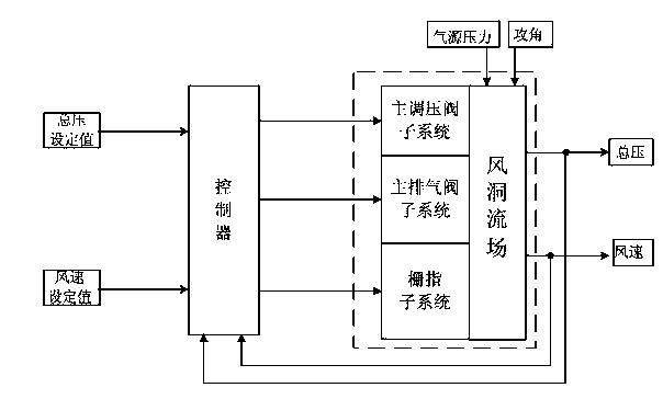
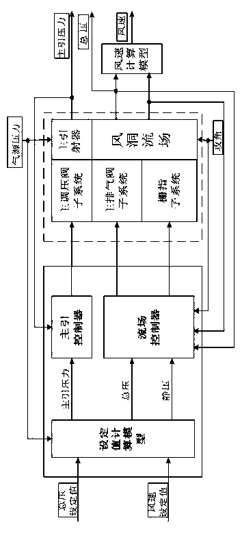
[0043] The structure of the flow field control system of the 2.4m temporary ejection type transonic wind tunnel is as follows: figure 1As shown, the generalized wind tunnel object is in the dotted box. In order to eliminate the influence of the reduction of the air source pressure on the flow field of the wind tunnel during the wind tunnel test, the main pilot pressure control loop is introduced, and the control of the wind tunnel flow field is decomposed into two parts: the main pilot pressure control and the total pressure static pressure control, as shown in figure 2 shown. The control structure is composed of three modules: the set value calculation model, the main pilot controller, and the flow field controller. In the main pilot pressure control part, the main pressure regulati...


PUM


Abstract

The invention relates to a high-precision temporary punching type injecting transonic speed wind tunnel flow field control structure and a method. According to the control structure, a wind tunnel flow field is decomposed into a main injection pressure control portion and a total pressure-static pressure control portion, and the control structure is mainly composed of such three modules as a set value calculation model, a main injection controller and a flow field controller. In the main injection pressure control portion, a main pressure regulating valve is adopted to control the main injection pressure. In the total pressure-static pressure control portion, the total pressure and the static pressure are controlled through a main air release valve and a gate finger. The set value calculation model is formed by a one-dimensional variable cross-section tube unsteady Euler equation set, and a main injection pressure set value and a static pressure set value of a wind tunnel model are solved through computational fluid dynamics software. The main injection controller is formed by using a segmented incremental PID control algorithm, and main injection pressure at an outlet of a main ejector is regulated. The flow field controller is formed by taking a model attitude feed-forward dynamic matrix control method as a core, the total pressure of a stable section and the static pressure of a test section are regulated. The control method is good in real-time performance and high in control precision, and variations of the Mach number in a test stage are controlled to a range of 0,001.

Description

technical field [0001] The invention relates to a high-precision control structure and method for a flow field of a temporary ejection type transonic wind tunnel, and the control precision of the Mach number of the flow field can reach 0.001. Background technique [0002] A wind tunnel is a tubular test device that produces a controllable and uniform airflow. It is an important ground simulation platform for studying the law of air flow, the aerodynamic characteristics of aerospace vehicles and other objects. Wind tunnel test is the main means of obtaining aircraft aerodynamic data, evaluating and analyzing layout design and predicting flight performance. Quality and level of development. [0003] As the main platform for aerodynamic tests, the impulsive jet transonic wind tunnel needs to solve the problems of high-precision flow field control and energy consumption reduction. The development of large aircraft (my country's C919 large passenger aircraft, ARJ aircraft, etc....

Claims


Application Information

Patent Timeline
IPC IPC(8): G05D16/20
Inventor 杜宁袁平芮伟于丰易凡张健金志伟张林饶正周秦建华龙秀虹马永一郁文山苏北辰陈龙蒋婧妍杨兴锐严翔
Owner INST OF HIGH SPEED AERODYNAMICS OF CHINA AERODYNAMICS RES & DEV CENT
Why Eureka
Try Eureka