
Control system of electric self-balance wheelbarrow and control method thereof

A control system and self-balancing technology, applied in the direction of single motor speed/torque control, vehicle components, rider drive, etc., can solve the problems of poor control stability and reliability, poor stability and reliability, and weak data processing capabilities of the main control chip and other issues, to achieve the effect of enriching the internal and external resources of the chip, stable and reliable control, and powerful digital computing capabilities

Inactive Publication Date: 2015-09-23
HEFEI UNIV OF TECH
View PDF3 Cites 6 Cited by
  • Summary
  • Abstract
  • Description
  • Claims
  • Application Information

AI Technical Summary

Problems solved by technology

In the domestic unicycle market, the data processing capability of the main control chip selected by the electric self-balancing unicycle is relatively weak, and due to the simple control algorithm, some even use an open-loop control method, resulting in poor stability and reliability of the unicycle control, and in the software Insufficient consideration of factors in the control program, incomplete protection program, seriously affecting the safety of the driver
[0003] In addition, domestic unicycle manufacturers only rely on gyroscopes or accelerometers to collect the inclination angle of the vehicle, and do not use the data fusion processing technology of the gyroscope and accelerometer. In this way, due to the vibration of the vehicle and other reasons, the inclination angle measurement accuracy is low. This leads to poor control stability and reliability

Method used


Image

  • Control system of electric self-balance wheelbarrow and control method thereof
  • Control system of electric self-balance wheelbarrow and control method thereof
  • Control system of electric self-balance wheelbarrow and control method thereof

Examples


Embodiment Construction

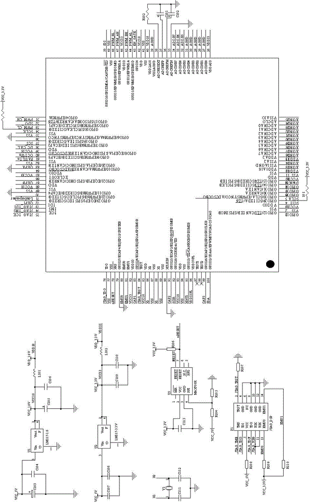
[0027] like figure 1 As shown, a control system of an electric self-balancing unicycle, including a 9-axis motion processing sensor for collecting angular velocity signals and acceleration signals, a DC brushless motor rotor position sensor for collecting DC brushless motor rotor position signals, and a control unit 10 and the DC brushless motor, the output terminals of the 9-axis motion processing sensor and the DC brushless motor rotor position sensor are all connected to the input terminal of the control unit 10, and the output terminal of the control unit 10 is connected to the input terminal of the DC brushless motor. The brushless motor outputs a torque signal to drive the wheel to rotate.

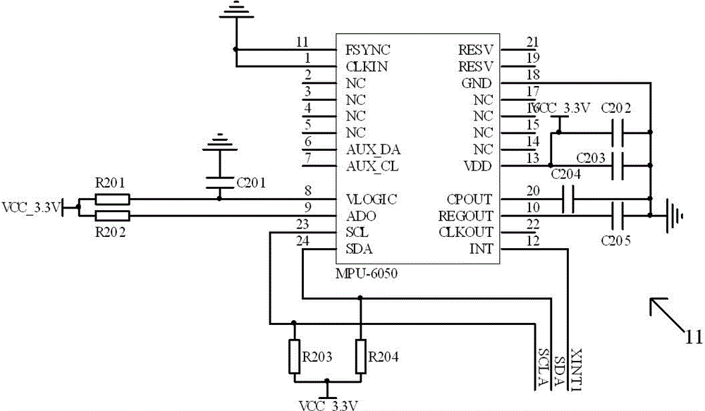
[0028] like figure 1 , 2 As shown, the control unit 10 is composed of a 9-axis motion processing sensor signal processing circuit 11, a brushless DC motor rotor position signal processing circuit 12, a main control chip and a brushless DC motor drive circuit 13, and the 9-axis moti...


PUM


Abstract

The present invention relates to a control system of an electric self-balance wheelbarrow, comprising a 9-axis motion processing sensor used for acquiring an angular velocity signal and an accelerated velocity signal, a DC brushless motor rotor position sensor used for acquiring a position signal of a rotor of a DC brushless motor, a control unit and the DC brushless motor, wherein output ends of the 9-axis motion processing sensor and the DC brushless motor rotor position sensor are connected with input ends of the control unit, and an output end of the control unit is connected with an input end of the DC brushless motor. The present invention also discloses a control method of an electric self-balance wheelbarrow. According to the control system and the control method of the present invention, a digital signal processor TMS320F2809 having abundant on-chip peripheral equipment resources and 100M strong digital operational capability is adopted, and the advanced 9-axis motion processing sensor is used for measuring the angular velocity and accelerated velocity of a vehicle, an accurate inclination angle of the electric self-balance wheelbarrow can be obtained through a sensor data fusion technology, and the DC brushless motor is controlled by a PID control algorithm, stable and reliable control can be achieved.

Description

technical field [0001] The invention relates to the technical field of unicycles, in particular to a control system and a control method of an electric self-balancing unicycle. Background technique [0002] At present, in China, unicycles have quietly become popular, and unicycles are no longer a special tool for special groups of people, but everyone can enjoy them. In the domestic unicycle market, the data processing capability of the main control chip selected by the electric self-balancing unicycle is relatively weak, and due to the simple control algorithm, some even use an open-loop control method, resulting in poor stability and reliability of the unicycle control, and in the software Insufficient consideration of factors in the control program and incomplete protection program seriously affect the safety of the driver. [0003] In addition, domestic unicycle manufacturers only rely on gyroscopes or accelerometers to collect the inclination angle of the vehicle, and ...

Claims


Application Information

Patent Timeline
Patent Type & Authority Applications(China)
IPC IPC(8): H02P6/08B62M6/45
Inventor 赵韩孙浩黄康甄圣超赵福民
Owner HEFEI UNIV OF TECH
Learn More