Internal combustion engine
A technology for internal combustion engines and nozzles, applied to internal combustion piston engines, combustion engines, mechanical equipment, etc., can solve problems such as nozzle hole corrosion
- Summary
- Abstract
- Description
- Claims
- Application Information
AI Technical Summary
Problems solved by technology
Method used
Image
Examples
no. 1 approach
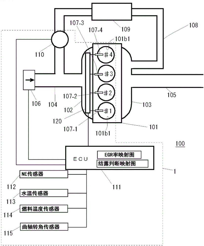
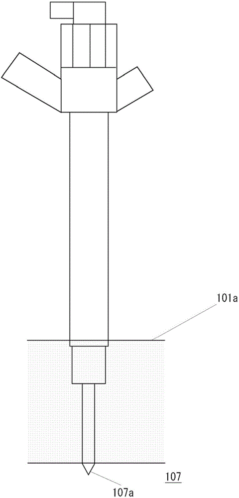
[0045] figure 1It is an explanatory diagram showing a schematic configuration of the internal combustion engine 100 of the first embodiment. The fuel injection device 1 is attached to the internal combustion engine 100 . The internal combustion engine 100 is an internal combustion engine implementing in-cylinder injection, more specifically, a diesel internal combustion engine. The internal combustion engine 100 is a four-cylinder. The internal combustion engine 100 includes an engine main body 101 including a cylinder head 101 a and a cylinder block 101 b, and the engine main body 101 includes #1 cylinders to #4 cylinders. The fuel injection device 1 is mounted on the internal combustion engine 100 . The fuel injection device 1 includes #1 injectors 107-1 to #4 injectors 107-4 corresponding to #1 cylinders to #4 cylinders. Specifically, the #1 injector 107-1 is attached to the #1 cylinder, and the #2 injector 107-2 is attached to the #2 cylinder. #3 injector 107-3 is att...
no. 2 approach
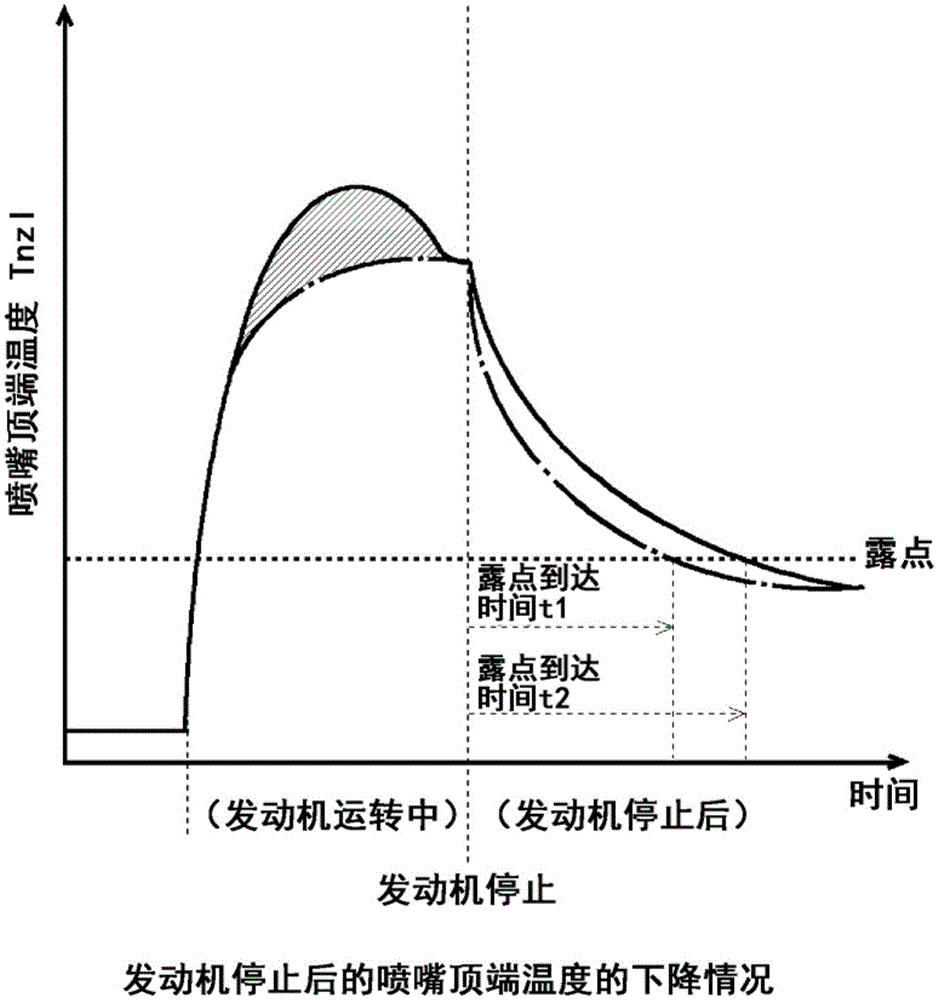
[0079] Next, refer to Figure 8 , Figure 9 , and the second embodiment will be described. Figure 8 It is a flowchart showing an example of the control of the internal combustion engine 100 in the second embodiment, specifically, the idle extension control. Figure 9 (A), Figure 9 (B) is a graph showing changes in nozzle tip temperature due to idle speed extension.
[0080] The second embodiment differs from the first embodiment in the content of the nozzle corrosion prevention control (control for reducing the heat dissipation rate of the nozzle) executed by the ECU 111 . In the second embodiment, instead of the idling execution control in the first embodiment, idling extension control is implemented instead. which is, Figure 4 The contents of steps S1 to S8 in the shown flowchart are the same as those in the first embodiment. Since the basic structure of the internal combustion engine 100 is the same as that of the first embodiment, a detailed description thereof wi...
no. 3 approach
[0094] Next, refer to Figure 10 to Figure 13 , and the third embodiment will be described. Figure 10 It is a block diagram showing main parts of the internal combustion engine 100 of the third embodiment. Figure 11 It is a flowchart showing an example of control of the internal combustion engine 100 in the third embodiment. Figure 12 It is an explanatory diagram schematically showing the cooling of the piston in the third embodiment. Figure 13 (A), Figure 13 (B) is a graph showing the effect of piston cooling.
[0095] when referring to Figure 10 and Figure 12 In this case, the internal combustion engine 100 of the third embodiment includes, as its main part, an electric oil pump 121 electrically connected to the ECU 111 . Such as Figure 12 As shown, the electric oil pump supplies oil to the oil injection hole 122 for cooling the piston 101c housed in the cylinder block 101b. The oil injection hole 122 is provided on each cylinder, and injects oil to the cooli...
PUM
 Abstract
Description
Claims
Application Information
 - R&D
- Intellectual Property
- Life Sciences
- Materials
- Tech Scout
- Unparalleled Data Quality
- Higher Quality Content
- 60% Fewer Hallucinations
Browse by: Latest US Patents, China's latest patents, Technical Efficacy Thesaurus, Application Domain, Technology Topic, Popular Technical Reports.
© 2025 PatSnap. All rights reserved.Legal|Privacy policy|Modern Slavery Act Transparency Statement|Sitemap|About US| Contact US: help@patsnap.com


