
Artificial temporal-mandibular joint replacement bone trimming guide plate assembly

A temporomandibular joint and guide plate technology is used in the field of artificial temporomandibular joint replacement bone trimming guide plate components, which can solve problems such as reducing the strength of the jaw, reducing nerves, and cerebrospinal fluid leakage, reducing bone loss, reducing the occurrence of complications, The effect of increasing the degree of fit

Active Publication Date: 2015-09-30
SHANGHAI NINTH PEOPLES HOSPITAL AFFILIATED TO SHANGHAI JIAO TONG UNIV SCHOOL OF MEDICINE
View PDF11 Cites 13 Cited by
  • Summary
  • Abstract
  • Description
  • Claims
  • Application Information

AI Technical Summary

Problems solved by technology

As for the revision of the jaw, there is no clinically applicable tool for bone revision in China. Therefore, the bone revision has a certain blindness and will cause unnecessary loss of bone mass.
Secondly, because the bone material to be ground by bone trimming is cortical bone, which is the hardest part of the jaw, blind grinding will greatly reduce the strength of the jaw, and the thickness of the zygomatic arch itself is relatively thin. Blind grinding may cause the upper prosthesis to be artificial. The glenoid fossa cannot be fixed with screws; again, because the maxillary zygomatic arch is located close to the skull base, the risk is high. If the grinding is too much, it may damage the skull base and cause cerebrospinal fluid leakage; and the inner side of the mandibular condyle is intramandibular The arteriovenous and vascular bundles are easy to damage and cause massive bleeding during bone trimming, so a guide plate is needed to assist in precise osteotomy to reduce the risk of nerve and blood vessel injury

Method used


Image

  • Artificial temporal-mandibular joint replacement bone trimming guide plate assembly
  • Artificial temporal-mandibular joint replacement bone trimming guide plate assembly
  • Artificial temporal-mandibular joint replacement bone trimming guide plate assembly

Examples


Embodiment Construction

[0018] The embodiments of the present invention are described in detail below. This embodiment is implemented on the premise of the technical solution of the present invention, and detailed implementation methods and specific operating procedures are provided, but the protection scope of the present invention is not limited to the following implementation example.

[0019] This embodiment is mainly used in total joint replacement treatment of temporomandibular joint ankylosis, advanced condylar osteoarthritis and various advanced condylar degeneration. Preoperatively based on the patient's CT data, use 3D reconstruction technology to accurately restore the patient's jaw model, and import the matching prosthesis data, and perform simulated implantation of the prosthesis on the digital jaw model, so as to determine the position and range of jaw grinding , direction and depth; CAD / CAM technology is used to design the osteotomy guide plate, and the digital design is transformed in...


PUM

PropertyMeasurementUnit
Widthaaaaaaaaaa
Thicknessaaaaaaaaaa

Abstract

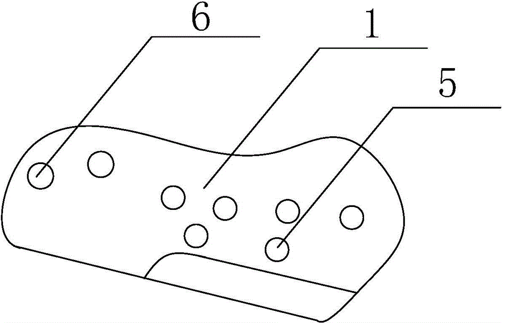
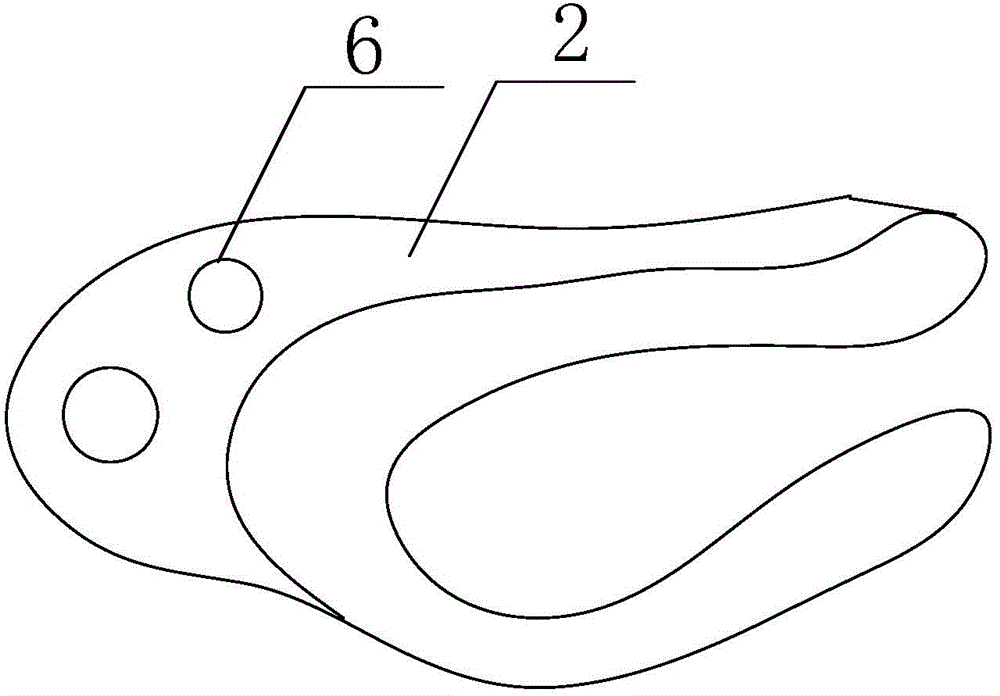
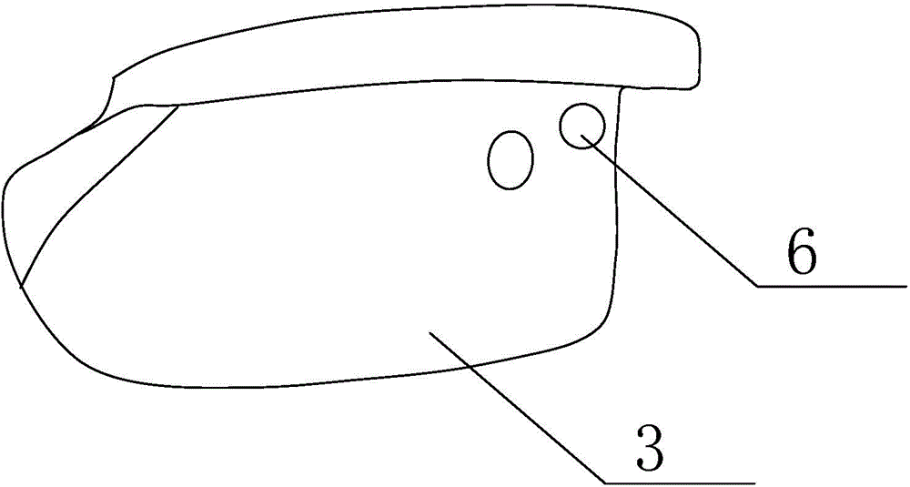
The invention discloses an artificial temporal-mandibular joint replacement bone trimming guide plate assembly. An articular tubercle guide plate is attached to the outer side face of the zygomatic arch, and the lower edge of the articular tubercle guide plate is in an edge shape or is provided with a shoulder. A zygomatic arch guide plate is attached to the outer surface of the zygomatic arch and is in a U shape, and the opening part of the U shape is in an edge shape. A condyle guide plate is attached to the outer surface of the condyle, and the upper edge of the condyle guide plate is in an edge shape or is provided with a shoulder. An ascending limb guide plate is attached to the outer surface of the mandible ascending limb, the upper portion of the ascending limb guide plate is hollowed out, and the hollowed-out part is in an edge shape. Bottom bone cutting of the maxilla articular tubercle, excision of the mandibular condyle and grinding of the outer surface of the zygomatic arch and the outer surface of the ascending limb are accurately guided, and the unnecessary bone loss is reduced.

Description

technical field [0001] The invention relates to a medical auxiliary device, in particular to an artificial temporomandibular joint replacement bone trimming guide plate assembly. Background technique [0002] The standard artificial temporomandibular joint cannot fully match the shape of the patient's jaw, so each patient must be modified to adapt to the shape of the prosthesis, mainly for the maxillary zygomatic arch, joint tubercle, mandibular condyle and outer ascending ramus. side. As for jaw modification, there is no clinical tool for guiding bone modification in China. Therefore, bone modification has certain blindness and will cause unnecessary loss of bone mass. Secondly, because the bone material to be ground by bone trimming is cortical bone, which is the hardest part of the jaw, blind grinding will greatly reduce the strength of the jaw, and the thickness of the zygomatic arch itself is relatively thin. Blind grinding may cause the upper prosthesis to be artifici...

Claims


Application Information

Patent Timeline
IPC IPC(8): A61F2/30
Inventor 何冬梅杨驰白果陆川
Owner SHANGHAI NINTH PEOPLES HOSPITAL AFFILIATED TO SHANGHAI JIAO TONG UNIV SCHOOL OF MEDICINE
Learn More