Eureka AIR delivers breakthrough ideas for toughest innovation challenges, trusted by R&D personnel around the world.

Fan housing bush assembling device

A technology of assembling device and fan cover, applied in metal processing, metal processing equipment, manufacturing tools, etc., can solve the problems of low work efficiency and high labor intensity of workers, and achieve the effect of easy control, saving manpower and reducing labor intensity of workers

Inactive Publication Date: 2015-09-30
德清京达电气有限公司
View PDF7 Cites 2 Cited by
  • Summary
  • Abstract
  • Description
  • Claims
  • Application Information

AI Technical Summary

Problems solved by technology

[0002] At present, inserting the bushing into the center hole of the corresponding fan casing is generally done entirely by manual operation, which results in low work efficiency and high labor intensity.

Method used


Image

  • Fan housing bush assembling device
  • Fan housing bush assembling device

Examples


Embodiment 1

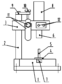
[0024] see figure 1 , in the figure, the fan casing bushing assembly device of the present invention includes a bracket, a support block 4, a support column 5 and a lifting sliding pressure block 6, wherein the bracket includes a base 1, a column 2 and a beam 3 connected in sequence, and the base is provided with Groove 7, the support block is fixed on the groove, the support column is fixed on the support block, the lifting sliding pressure block is set in the sliding groove on the beam, the lower part of the lifting sliding pressure block is facing the support column, and the lifting sliding pressure block is also driven mechanism.

[0025] The driving mechanism of the lifting sliding briquetting block is an air cylinder or hydraulic cylinder 8, wherein the cylinder body of the air cylinder or hydraulic ram is fixed on the beam, and the piston rod of the air cylinder or hydraulic ram is directly connected with the lifting sliding briquetting block. The top of the column is ...

Embodiment 2

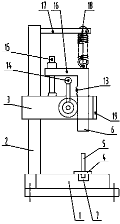
[0028] see figure 2 , in the figure, the structure of this embodiment is similar to that of Embodiment 2, and the same parts will not be repeated here. The difference is that the driving mechanism for lifting and sliding pressure blocks described in this embodiment includes a rack and pinion transmission mechanism 13 and an operating handle 14 , wherein the gear is installed in the beam through the rotation of the shaft, and a row of racks is arranged up and down on the side of the lifting sliding pressure block facing the gear installation, the gear and the rack are meshed for transmission, and the operating handle is fixedly installed on one end of the gear shaft.

[0029] A guiding mechanism and an automatic reset mechanism are provided at the top of the lifting and sliding pressure block. Described guide mechanism comprises guide rod 15, and guide rod is fixed on the crossbeam, and the top of lifting sliding pressure block is provided with flange 16, and wherein flange pa...


PUM


Abstract

The invention belongs to the technical field of production of vehicle-mounted fans, and particularly relates to a fan housing bush assembling device which comprises a support, a supporting block, a supporting column and a lifting sliding press block. The support comprises a base, a stand column and a cross beam connected in sequence. A groove is formed in the base, the supporting block is fixed on the groove, and the supporting column is fixed on the supporting block. The lifting sliding press block is sleeved with a sliding groove in the cross beam, and the lower portion of the lifting sliding press block right faces the supporting column. A lifting sliding press block driving mechanism is further included. The fan housing bush assembling device is simple in structure, convenient to operate and use, capable of remarkably improving work efficiency and lowering labor intensity of workers, stable and reliable in transmission, flexible and diversified in structure type and quite suitable for application and popularization due to multiple embodiments.

Description

technical field [0001] The invention belongs to the technical field of vehicle-mounted fan production, and in particular relates to a fan casing bush assembly device. Background technique [0002] At present, inserting the bushing into the central hole of the corresponding fan casing is generally done entirely by manual operation, which results in low work efficiency and high labor intensity. Therefore, it is of great significance to study and design an auxiliary device for inserting the bushing into the center hole of the fan casing, thereby improving the work efficiency of the workers and reducing the labor intensity of the workers. Contents of the invention [0003] The technical problem to be solved by the present invention is to overcome the deficiencies of the above-mentioned prior art, and provide a fan casing bush assembly device with simple structure, convenient operation and use, which can improve work efficiency and reduce labor intensity of workers. [0004] I...

Claims


Application Information

Patent Timeline
Patent Type & Authority Applications(China)
IPC IPC(8): B23P19/027
CPCB23P19/027
Inventor 钱斌斌
Owner 德清京达电气有限公司
Why Eureka
Eureka Blog
Learn More