Hot melt cementing machine

A technology of hot-melt glue and heating plate, which is applied in book binding, binding adhesives, printing, etc., can solve the problems of non-removable transport of cardboard, non-parallel front push plates, inconvenient packaging costs, etc., and achieve Increase the effect of full integration, easy transportation, and small size

Active Publication Date: 2015-09-30
RAYSON ELECTRICAL MFG
View PDF6 Cites 3 Cited by
  • Summary
  • Abstract
  • Description
  • Claims
  • Application Information

AI Technical Summary

Problems solved by technology

[0004] The purpose of the present invention is to provide a hot-melt glue binding machine, aiming to solve the technical problems of the existing glue binding machine that the front push plates are not parallel, and the non-removable cardboard prevents transportation and high packaging costs.

Method used


Image

  • Hot melt cementing machine
  • Hot melt cementing machine
  • Hot melt cementing machine

Examples


Embodiment Construction

[0026] In order to make the object, technical solution and advantages of the present invention more clear and definite, the present invention will be further described in detail below with reference to the accompanying drawings and examples.

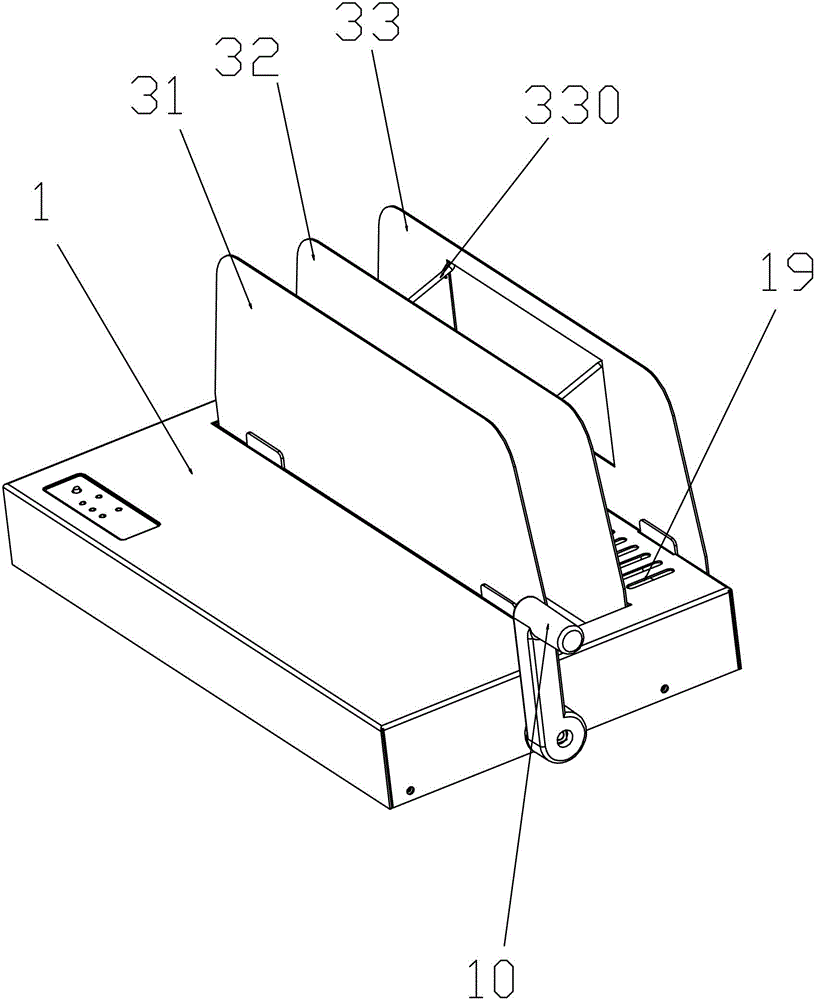
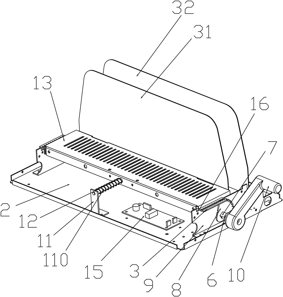
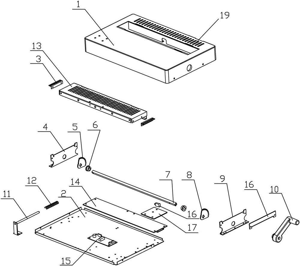
[0027] Such as Figure 1-5 As shown, the present invention discloses a hot-melt adhesive machine, which includes a housing 1, a sliding plate 13, a sliding rack 3, a left bracket 4, a left gear 5, a shaft sleeve 6, a transmission shaft 7, a right gear 8, and a right bracket 9 handle 10, spring bracket 11, spring 12, base 2, heating plate 14, controller 15, sliding rack pressing plate 16, glass fiber heat insulation board 17 and vibrator 18; wherein, the left bracket 4 and the right bracket 9 is fixedly installed on the base 2; the shaft sleeves 6 are inserted into the round holes on the left bracket 4 and the right bracket 9 respectively; the two ends of the transmission shaft 7 pass through the shaft sleeves 64 respectively, and are ins...


PUM


Abstract

The invention discloses a hot melt cementing machine which comprises a base, a shell and a sliding mechanism, wherein the sliding mechanism is mounted on the base; the shell is mounted on the sliding mechanism; the hot melt cementing machine further comprises a detachable paper baffle structure, a heating plate and a controller; the sliding mechanism comprises a sliding plate, brackets, a transmission shaft, gears, sliding racks and a spring bracket; the brackets are fixed on the base; the transmission shaft penetrates through the brackets at the two ends of the base respectively; the sliding racks are arranged at the two ends of the sliding plate and are mounted in inner slots of the brackets at the two ends; the transmission shaft penetrates through the gears; the gears are meshed with the sliding racks; the transmission shaft drives the gears; the gears drive the sliding racks to slide in the inner slots of the brackets; the heating plate and the controller are mounted on the base; the controller is electrically connected with the heating plate; the spring bracket is mounted on the base; the detachable paper baffle structure comprises three detachable paper baffles; the three detachable paper baffles are respectively mounted on the shell and the sliding plate.

Description

technical field [0001] The invention relates to the field of hot-melt glue equipment, in particular to a hot-melt glue machine. Background technique [0002] The sliding structure of the existing glue binding machine uses drawer guide rails for sliding. This structure tends to cause uneven left and right when pushed forward, which makes the bound documents not straight enough. The paper stopper is welded together with the base. Large, increases the package cost and shipping cost. In addition, the return spring mechanism provided on both sides of the guide rail of this type of sliding glue binding machine, after the spring working performance changes, it is easy to cause inconsistent thrusts at the left and right ends when pushing, and the bound documents are not smooth; and the existing sliding structure Grab handles are laborious to use and expensive to manufacture. [0003] Therefore, the prior art still needs to be improved and developed. Contents of the invention ...

Claims


Application Information

Patent Timeline
IPC IPC(8): B42C9/00
Inventor 陈勇军
Owner RAYSON ELECTRICAL MFG
Why Eureka
Try Eureka