Automatic feeding device for capacitors

A technology of automatic feeding and capacitors, applied in conveyor control devices, vibrating conveyors, transportation and packaging, etc., can solve the problems of capacitor guide pins falling to the ground, damage to capacitor guide pins, and damage to the quality of capacitor guide pins. The effect of reducing physical damage and increasing automation

Active Publication Date: 2015-09-30
益阳市鹏程科技发展有限公司
View PDF10 Cites 18 Cited by
  • Summary
  • Abstract
  • Description
  • Claims
  • Application Information

AI Technical Summary

Problems solved by technology

[0002] In the capacitor, the guide pin of the capacitor is the key factor to determine the quality of the capacitor. When the guide pin of the capacitor is wound, it is transported through the vibrating conveying plate. At the junction of the feed guide groove, it is very easy for the guide pin to fall off, causing the capacitor guide pin to fall to the ground and damage the quality of the capacitor guide pin. It is difficult to transport the guide pin into the guide pin conveying groove through the vibration of the disc body, and the operator needs to use external objects to clamp or guide the guide pin into the guide pin conveying groove, and then convey it to the guide needle outlet by the conveying groove. During the guiding or clamping process, it is very easy to damage the capacitor guide pin, reducing the quality of the capacitor and the yield of the capacitor

Method used


Image

  • Automatic feeding device for capacitors
  • Automatic feeding device for capacitors
  • Automatic feeding device for capacitors

Examples


Embodiment

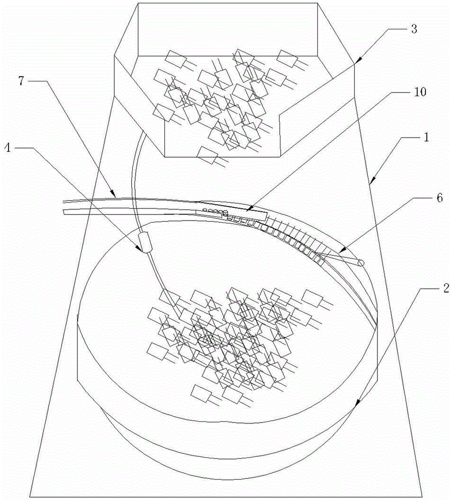
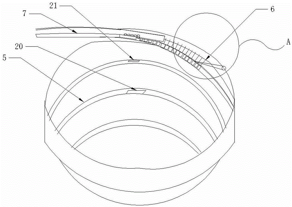
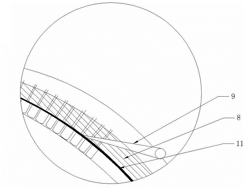
[0024] Such as Figure 1~Figure 4 The shown automatic feeding device for a capacitor includes a frame 1, a vibrating plate 2 is provided on the frame 1, and a material box 3 for feeding is provided above the vibrating plate 2, and the material box 3 is controlled by a controller. The vibrating frame is installed on the frame 1, and the vibrating plate 2 is equipped with a detection device 4 connected with the controller to detect whether there is material in the vibrating plate 2. The inner wall of the vibrating plate 2 is provided with a spiral upward feeding track 5, and the material feeding The end of the track 5 is provided with a capacitor array assembly 6 , and the end of the capacitor array assembly 6 is connected to the conveying trough 7 . The capacitor alignment assembly 6 includes a magnetically conductive shaping plate 8, an electromagnet, an alignment needle 9 and a steering assembly 10; the magnetically conductive shaping plate 8 is arranged along the inner w...


PUM


Abstract

The invention provides an automatic feeding device for capacitors. The automatic feeding device comprises a rack. A vibrating plate is arranged on the rack. A work bin used for feeding is arranged above the vibrating plate and installed on the rack through a vibrating rack controlled by a controller. The vibrating plate is provided with a detecting device which is connected with the controller and used for detecting whether materials exist in the vibrating plate. A material conveying track spiral upwards is arranged on the inner wall of the vibrating plate. A capacitor array assembly is arranged at the tail end of the material conveying track. The tail end of the capacitor array assembly is connected with a conveying groove. According to the automatic feeding device for the capacitors, the capacitors are conveyed upwards along the material conveying track spiral upwards and automatically arranged into a row to enter the conveying groove at the tail end of the capacitor array assembly to enter the next working procedure when passing through the capacitor array assembly.

Description

technical field [0001] The invention relates to a feeding device, in particular to an automatic feeding device for capacitors. Background technique [0002] In the capacitor, the guide pin of the capacitor is the key factor that determines the quality of the capacitor. When the guide pin of the capacitor is wound, it is transported through the vibrating conveyor plate. At the junction of the feed guide groove, it is very easy for the guide pins to fall off, causing the capacitor guide pins to fall to the ground and damage the quality of the capacitor guide pins. In the existing conveying tray, a small amount of guide pins at the bottom of the tray are very It is difficult to transport the guide pin into the guide pin conveying groove through the vibration of the disc body, and the operator needs to use external objects to clamp or guide the guide pin into the guide pin conveying groove, and then convey it to the guide needle outlet by the conveying groove. During the gu...

Claims


Application Information

Patent Timeline
Patent Type & Authority Applications(China)
IPC IPC(8): B65G27/02B65G47/28B65G43/08
Inventor 付笑蝉付云蛟罗春文包浩雷
Owner 益阳市鹏程科技发展有限公司
Why Eureka
Try Eureka