Sewage treatment area for vertical multistage AO ecological sewage treatment tank
A technology of sewage treatment tank and treatment area, applied in aerobic and anaerobic process treatment and other directions, can solve the problems of high construction cost and limited sewage treatment capacity, so as to improve efficiency, improve sewage treatment effect, and prolong anaerobic degradation. effect of time
- Summary
- Abstract
- Description
- Claims
- Application Information
AI Technical Summary
Problems solved by technology
Method used
Image
Examples
Embodiment approach 1
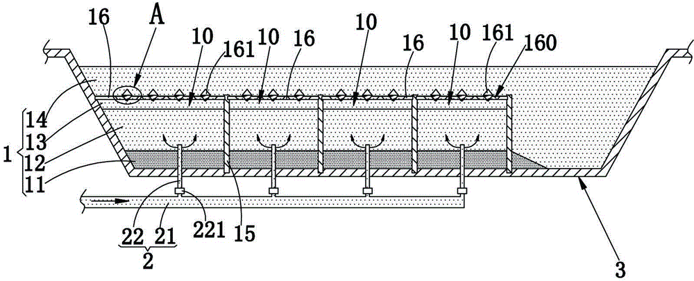
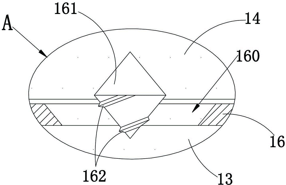
[0021] refer to figure 1 , figure 2 , used in the sewage treatment area of the vertical multi-stage AO ecological sewage treatment pool, the treatment area 1 is composed of a sludge layer 11, an anaerobic layer 12, anoxic layer 13 and an aerobic layer 14 which are stacked sequentially from bottom to top, In the treatment area 1, a plurality of partitions 10 are formed by dividing by criss-cross partitions 15, and the top of the partitions 15 is located at the junction of the aerobic layer 14 and the anoxic layer 13; the top cover of each partition 10 is provided with a ballast Plates 16, each ballast plate 16 is provided with at least three through holes 160, and the through holes 160 are all in the shape of a tapered hole with a large top and a small bottom. The structure setting of the ballast plate 16 creates certain resistance to the sewage flowing upwards, so that the sewage forms convection between the anaerobic layer 12 and the anoxic layer 13, thereby prolonging th...
Embodiment approach 2
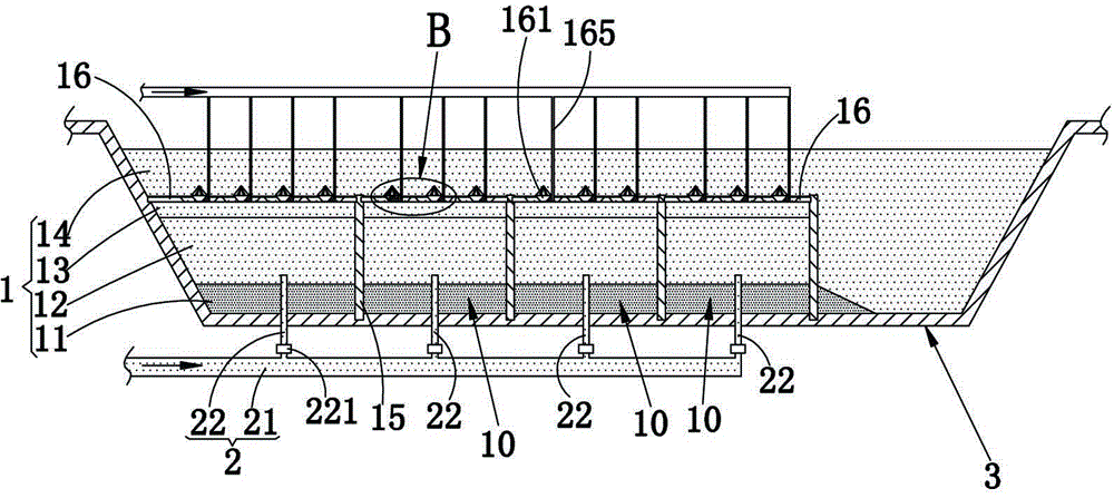
[0025] The difference between this embodiment and Embodiment 1 is that: refer to image 3 , Figure 4 , the guide body 161 of the present embodiment is a hollow structure, and the upper cone wall of the guide body 161 is provided with several air outlet holes 167, and the lower cone wall of the guide body 161 is provided with several water holes, or as image 3 , Figure 4 As shown, the water hole 163 is arranged at the bottom of the guide body 161, and the inside of the guide body 161 is equipped with an aerobic filler 164 and / or anoxic filler 164, and the guide body 161 is also equipped with a gas supply pipe for connecting to it. The aeration pipe 165 constitutes an aeration structure. The air blown into the aeration pipe 165 is discharged upwards from the air outlet 167, and the sewage flowing upwards from the anoxic layer 13 can also enter the guide body 161 through the water hole 163, and the sludge entering the guide body 161 can also pass through the water guide body...
Embodiment approach 3
[0027] The difference between this embodiment and Embodiment 1 is that: refer to Figure 5 , Image 6 The aeration structure of this embodiment adopts the conventional aeration device 17 in the prior art, and the aeration device 17 is arranged above each through hole 160, and the aeration device 17 is assembled on the above-mentioned ballast plate 16. In addition, refer to Image 6 , the wall of the through hole 160 is also provided with a helical groove 166, the setting of the helical groove 166 can play a certain diversion effect on the sewage flowing through the through hole 160, so that it forms a certain swirl flow, and further improves the aerobic flow of the sewage. The diffusion rate of layer 14.
PUM
 Abstract
Description
Claims
Application Information
 - R&D
- Intellectual Property
- Life Sciences
- Materials
- Tech Scout
- Unparalleled Data Quality
- Higher Quality Content
- 60% Fewer Hallucinations
Browse by: Latest US Patents, China's latest patents, Technical Efficacy Thesaurus, Application Domain, Technology Topic, Popular Technical Reports.
© 2025 PatSnap. All rights reserved.Legal|Privacy policy|Modern Slavery Act Transparency Statement|Sitemap|About US| Contact US: help@patsnap.com


