A device for self-positioning and automatically pressing power-in components and its installation method

A self-positioning technology for power-in components, applied in the direction of gaseous chemical plating, metal material coating process, coating, etc., can solve the problem of shortening the service life of power-in components, irregular operations by operators, and affecting the life of power-in components, etc. problems, to achieve protection stability, reduce product scrap rate, and ensure the effect of electrode contact stability

Active Publication Date: 2017-09-26
HANERGY MOBILE ENERGY HLDG GRP CO LTD
View PDF5 Cites 0 Cited by
  • Summary
  • Abstract
  • Description
  • Claims
  • Application Information

AI Technical Summary

Problems solved by technology

[0003] However, due to the strict control of high temperature and time when entering and exiting the furnace during the production process, the operator's operation is not standardized, the connector of the power supply component is easy to loosen and be pulled out, and the card slot lacks a buffer part, resulting in uneven force, etc., so that The service life of the power supply components is greatly shortened, which seriously affects the life of the power supply components
Secondly, when the existing gold-plated cylindrical electrode head is plugged into the electrical component, it is easy to scratch the gold-plated layer on the surface of the cylinder, which is easy to oxidize and reflect
Every time there is a reflection, you need to use a 2mm inner hexagon to loosen the two fastening screws on the lock seat to check the oxidation wear and looseness of the electrode head of the workpiece holder and the oxidation of the copper plate, and then remove the lock seat. At this time, the following are likely to occur Two problems: 1. The inner hexagonal sliding wire; 2. The lock seat is stuck
Every time the above situation occurs, it is time-consuming and labor-intensive. It is necessary to use a syringe to drip lubricating oil. One person uses carp pliers to shake back and forth, and one person uses carp pliers to pull out hard to remove the lock seat, which brings a lot of inconvenience to the operator.

Method used


Image

  • A device for self-positioning and automatically pressing power-in components and its installation method
  • A device for self-positioning and automatically pressing power-in components and its installation method
  • A device for self-positioning and automatically pressing power-in components and its installation method

Examples


Embodiment Construction

[0048]In order to make the object, technical solution and advantages of the present invention clearer, the present invention will be further described in detail below with reference to the accompanying drawings and examples.

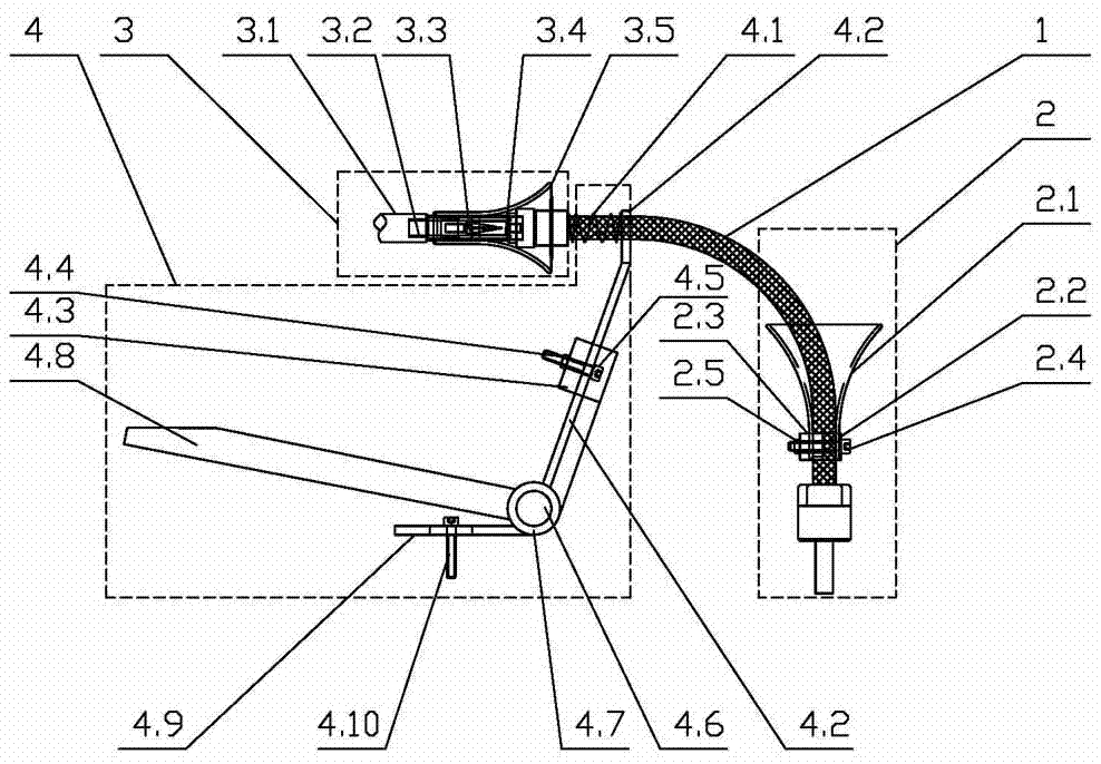
[0049] The stability of the coating process of each electrode in the deposition furnace requires that the electrode contact of the plasma-enhanced chemical vapor deposition device must be good. According to the principle of leverage, this invention designs a new type of self-positioning and automatically pressing power-in components device, which can reduce the manpower and material resources required for production and maintenance, improve the service life of power-in components and reduce production without affecting the original functions. cost. In addition, the self-positioning and automatically pressing power-feeding component device can make the electrodes contact better.

[0050] like Figure 1 to Figure 14 As shown, this kind of self-positionin...


PUM


Abstract

The invention relates to an automatic self-positioning compress electricity inlet component device and an installing method thereof. The automatic self-positioning compress electricity inlet component device comprises an electricity inlet component protection mechanism and an automatic compressing electricity inlet component mechanism; the electricity inlet component protection mechanism comprises a horn mouth clamped groove which sleeves an electricity inlet component, is fixed to the electricity inlet component, and can completely eradicate stress concentration to conduct 360-degree protection in the working process of the electricity inlet component; the horn mouth clamped groove comprises a taper-shaped hexagonal fastening electrode tip, a taper-shaped electrode female head, a shielding tube and a positioning horn mouth lock bracket, wherein the shielding tube is installed on an electrode stem, the positioning horn mouth lock bracket sleeves the shielding tube and can promote an electricity inlet component to position automatically, the situation of the taper-shaped hexagonal fastening electrode tip can be observed conveniently at the same time, and the taper-shaped electrode female head is automatically positioned and connected with the taper-shaped hexagonal fastening electrode tip through a taper-shaped face; the automatic compressing electricity inlet component mechanism is a lever automatic compressing mechanism which promotes the electricity inlet component automatically to be compressed in a PECVD working procedure when a workpiece frame enters a depositing furnace and moves to a location and promotes electricity inlet component to loosen automatically at the same time when the technology is finished and discharging is conducted and the workpiece frame leaves limitation of the depositing furnace.

Description

technical field [0001] The invention belongs to the technical field of thin-film solar photovoltaic cells, and is applied to the positioning and compacting of power-feeding components in a PECVD deposition furnace, in particular to a self-positioning and automatic compacting power-feeding component device and an installation method thereof. Background technique [0002] At present, in order to maintain the stability of the coating process of each electrode in the deposition furnace, the electrode contact of the plasma-enhanced chemical vapor deposition device must be good. Therefore, it is required that after the workpiece rack enters the deposition furnace and moves in place, the operator needs to wear high-temperature gloves to insert the 18 power-feeding components into the lock seat one by one and press the handle of the lock seat; before the workpiece rack is pulled out of the deposition furnace, it is necessary to Manually pull out 18 power-in components. [0003] How...

Claims


Application Information

Patent Timeline
Patent Type & Authority Patents(China)
IPC IPC(8): C23C16/44
Inventor 智海龙
Owner HANERGY MOBILE ENERGY HLDG GRP CO LTD
Why Eureka
Try Eureka