Heater arrangement

A heater and commutator technology, applied in water heaters, fluid heaters, heating methods, etc., can solve problems such as pressure rise, damage, noise, etc., and achieve the effect of reducing assembly accuracy and cost

Inactive Publication Date: 2015-09-30
DANFOSS AS
View PDF5 Cites 0 Cited by
  • Summary
  • Abstract
  • Description
  • Claims
  • Application Information

AI Technical Summary

Problems solved by technology

This can cause a sudden increase in pressure which can not only cause a noticeable and annoying noise in the heating unit to which the heater is connected, but can also cause serious injury
[0007] Therefore, the valve body of a valve suitable for such a heater device has a relatively complicated structure
This structure increases the manufacturing cost

Method used


Image

  • Heater arrangement
  • Heater arrangement
  • Heater arrangement

Examples


Embodiment Construction

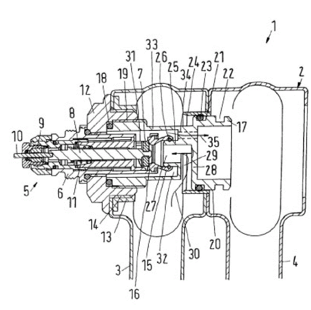
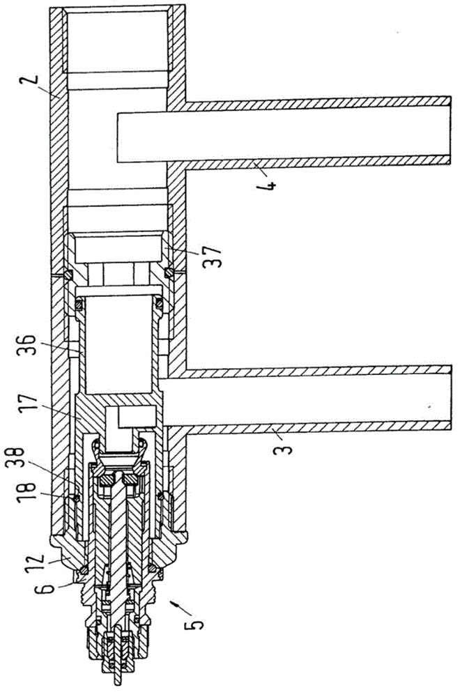
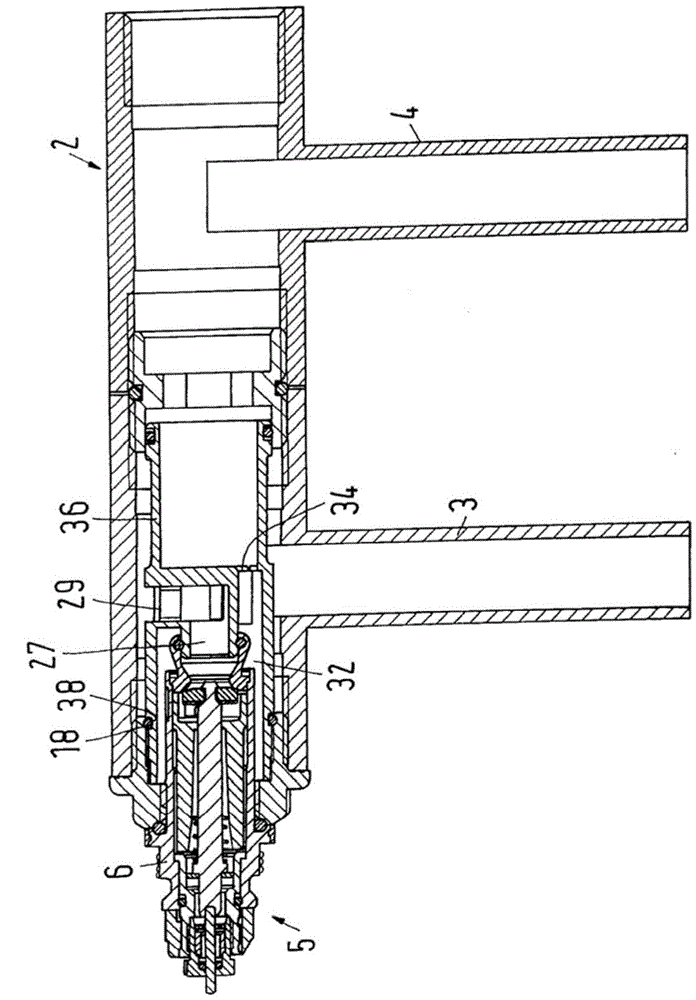
[0025] figure 1 A sectional view of a heater arrangement 1 is shown, which comprises a heater 2 designed as a segmented heater with a first section 3 and a second section 4 . Further segments of the heater are connected to the second segment 4 in a manner not shown in greater detail.

[0026] In a heater 2 of this type, the first section 3 is repeatedly used as a water inlet section for a heat transfer fluid, especially hot water, to flow through the heater. The remaining section 4 is used as a return section. However, all segments 3, 4 are used as heat exchange surfaces.

[0027] A valve 5 is provided for controlling the flow of heat transfer fluid through the heater 2 . The valve 5 has a valve body 6 in which a valve element 7 is movably arranged. The valve member 7 is moved via a shaft 8 which in turn acts via an actuating pin 10 which passes through the gland 9 . An end cover, not shown in detail, usually a thermostatic valve cover, acts on the actuating pin 10 . The...


PUM


Abstract

The arrangement (1) has a heater (2) i.e. sectional radiator, and a valve (5) comprising a valve element that is supported adjustably at a valve housing (6). The housing is connected with a sleeve (12) that is connected with the heater. A flow separator (17) forms a closure with a part of the heater, separates an inflow from an outflow of the valve, and is connected with the sleeve. The separator has a sealing zone that cooperates with the heater part and has a cylindrical peripheral surface (20), where two circumferential slots (21, 22) are arranged in the peripheral surface.

Description

[0001] This application is a divisional case of an invention patent application with the application number 200810125816.1, the application date is February 5, 2008, the priority date is February 6, 2007, the applicant is Danfoss, and the invention name is "heater device" Application. technical field [0002] The invention relates to a heater device having a heater, in particular a segmented heater, and a valve having a valve body and a valve seat movably arranged on a valve body, wherein, The valve body is connected with the casing, and the casing is connected with the heater. Background technique [0003] A heater arrangement of this type is known, for example, from DE 295 02 860 U1. [0004] Sectional heaters are also often referred to as "tube heaters" and typically use the first section of the heater as the inlet section. Accordingly, the valve must be able to control the flow of heat transfer liquid through the first section or at least from the first section into th...

Claims


Application Information

Patent Timeline
Patent Type & Authority Applications(China)
IPC IPC(8): F24H1/22F24H9/18F24H9/20F24D19/00F24D19/10
CPCF24D19/0012F24D2220/2018F24D19/0004F24D19/1018F24D19/1015
Inventor 詹姆斯.梅斯默泽伦.H.泽伦森保罗.霍尔格
Owner DANFOSS AS
Why Eureka
Try Eureka