Cable peeler

A peeler and cable technology, applied in the direction of circuits, lines/collector parts, electrical components, etc., can solve the problems of inability to rotate, difficult peeling, inconvenient rotation of cables, etc., to achieve enhanced rigidity and strength, and complete peeling operations , The effect of convenient peeling operation

Inactive Publication Date: 2015-09-30
象山石浦浦江工具厂 +1
View PDF3 Cites 4 Cited by
  • Summary
  • Abstract
  • Description
  • Claims
  • Application Information

AI Technical Summary

Problems solved by technology

[0004] 1) For the cable stripper of the first structure, it installs a cable guide mechanism at one end of the vertical installation plate, and the guide mechanism is provided with guide wheels, and is adjusted radially according to the diameter of the cable, and the vertical installation plate The other end is equipped with a stripping knife, which can also be adjusted radially according to the diameter of the cable, but its stripping knife is perpendicular to the axis of the cable, and the stripping knife is fixedly connected to the vertical mounting plate, installed vertically The plate is welded on the base, in other words, the entire cable stripper cannot be moved or rotated. If the cable stripping operation is to be performed, the cable must be rotating, so that the purpose of cable stripping can be achieved; therefore, this operation It is very unreasonable, the length of the cable is very long, turning the cable will inevitably cause the twist of the cable, and for the thicker cable, it is not only inconvenient to rotate the cable, but also cause the deformation of the cable;
[0005] 2) For the cable stripper of the second structure, the guiding mechanism of the cable is designed as a three-point positioning structure, and the three guiding mechanisms are evenly distributed along the circumferential direction, and a handle is provided on the fixed frame. Therefore, After the cable is positioned by three stroke guide adjustment assemblies, the handle is rotated, and the blade on the blade adjustment assembly arranged between the two guide mechanisms is used for peeling. In other words, the cable does not need to be rotated during operation. While the stripper rotates, the cable is stripped; however, it has the following problems: first, the blade is directed to the cable vertically, and when the stripper rotates, the blade will cut into the cable cortex, but the cable will be cut when the cable is pulled axially. It will be subject to great resistance, thereby making it difficult to operate and reducing production efficiency; secondly, the three stroke guide adjustment assemblies and the blade adjustment assembly are screwed in and out simultaneously through the same adjustment nut, so they cannot be rotated separately It is also inconvenient to adjust the positioning of the cable and the cutting amount of the cutter head for peeling;
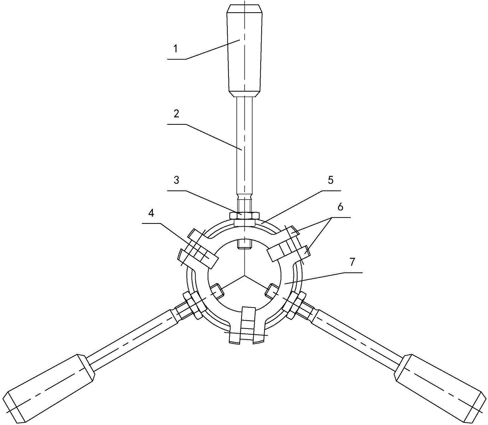
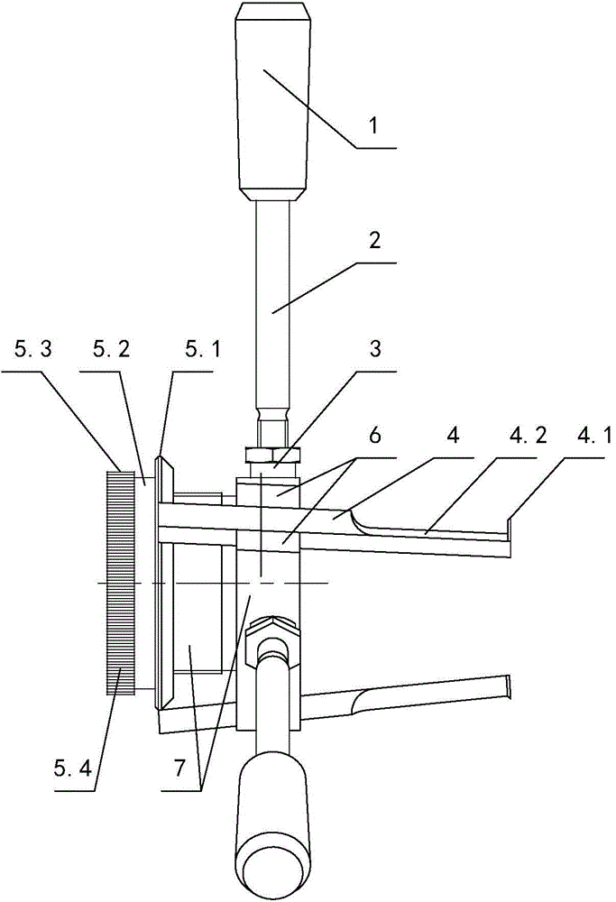
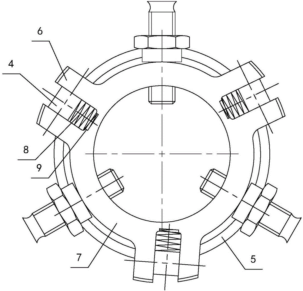
[0006] 3) For the cable stripper with the third structure, a three-point positioning guide mechanism is also used. The three guide mechanisms and the cutter head mechanism are evenly distributed along the circumferential direction, and the three guide mechanisms and the cutter head mechanism are all able to According to the diameter of the cable, the amount of positioning and expansion and the feed of the cutter head can be adjusted independently; when in use, put the fixing sleeve on the cable, rotate the fixing column and the cutter body fixing frame, so that the top of the fixing column and the cutter body fixing frame Clamp the cable sheath, and then pull the fixed sleeve, the cable sheath is cut by the cutter body; however, the cable is pulled axially, and the cutting marks of the cutter head are axial straight lines, that is to say, the cable sheath is cut axially. However, the radial cutting of the sheath still requires the cutter head assembly to rotate around the cable. At this time, except for the cutting marks, most of the area of ​​the sheath is still in contact with the inner core wire of the cable. Therefore, manual follow-up operations are still required for peeling. There are great difficulties and low production efficiency
[0007] To sum up, in the prior art, the cable stripper either keeps the cutter body, rotates the cable or pulls the cable, or the cable does not move, and the cutter body rotates to cut the cable sheath radially. The operations brought by these structures are very difficult. Trouble, greatly reducing production efficiency

Method used


Image

  • Cable peeler
  • Cable peeler
  • Cable peeler

Examples


Embodiment Construction

[0030] The present invention will be described in further detail below in conjunction with the accompanying drawings and specific embodiments.

[0031] Depend on Figure 1 to Figure 4As can be seen from the schematic structural diagram of the cable peeler of the present invention, it includes a handle 1, a cable fixing sleeve 7, a cable clamping device and a cutter head assembly, and the cable clamping device and the cutter head assembly are connected to the cable fixing sleeve 7 superior. There are three groups of cable clamping devices, which are hinged on the side wall of the cable fixing sleeve 7 along the circumferential direction. There are three groups of cutter head assemblies, which are evenly distributed on the side wall of the cable fixing sleeve 7 along the circumferential direction, and are arranged alternately with the cable clamping device. There are three handles 1, which are respectively connected to the ends of the cable clamping device. The cable peeler a...


PUM


Abstract

The invention discloses a cable peeler, comprising handles, a cable fixing sleeve, cable clamping units and cutter head assemblies, wherein the cable clamping units and the cutter head assemblies are all connected on the cable fixing sleeve. The three cable clamping units are uniformly distributed on the side wall of the cable fixing sleeve along the circumference. The three cutter head assemblies are hinged on the side wall of the cable fixing sleeve along the circumference. The three cable clamping units and the three cutter head assemblies are distributed in an alternate manner. The three handles are respectively connected to end portions of the cable clamping units. The cable peeler also comprises a cutter-head angle adjuster, which is screwed to one end of the cable fixing sleeve and is connected with the cutter head assemblies. By adopting such a structure, the cut-in angle and the cut-in depth of a cutter head can be randomly controlled, therefore making it very convenient to peel a cable and improving the production efficiency. In addition, a cable sheath is helically peeled off while the cutter head is screwed to conduct the cut-in operation, so that the cable sheath can be completely peeled off.

Description

technical field [0001] The invention relates to the field of hand tools, in particular to a cable peeler for power line construction. Background technique [0002] At present, in the process of power line construction, all protective screens, terminal box loops and power line wiring involve cable stripping. Electric workers usually use traditional cable hooks to strip cables. This operation mode is laborious and laborious. , and the problems of hook knife wounding, damage to insulation, and cable and hook knife scrapping often occur in the peeling process. Therefore, special-purpose cable stripping tools have occurred in the prior art, and the patent of the cable stripper with the publication number CN202906305U as disclosed on the website of the State Intellectual Property Office includes a base and a vertical mounting plate, and the vertical mounting plate is provided with a cable The traveling through hole, the periphery of the cable traveling through hole is evenly dist...

Claims


Application Information

Patent Timeline
Patent Type & Authority Applications(China)
IPC IPC(8): H01R43/28
CPCH01R43/28
Inventor 卓坚松
Owner 象山石浦浦江工具厂
Why Eureka
Try Eureka