Automatic charging pile

A technology of automatic charging and charging gun, which is applied in the direction of current collectors, electric vehicles, electrical components, etc., can solve the problems of manual operation, inconvenient use, and potential safety hazards, and achieve the goals of avoiding aging or damage, convenient use, and avoiding electric shock accidents Effect

Active Publication Date: 2015-09-30
ARTOP DESIGN GRP CO LTD
View PDF4 Cites 11 Cited by
  • Summary
  • Abstract
  • Description
  • Claims
  • Application Information

AI Technical Summary

Problems solved by technology

[0006] The purpose of the present invention is to provide an automatic charging pile, which aims to solve the problems in the prior art that the wires of the charging pile are exposed and the charging interface is exposed, which leads to inconvenient use, troublesome operation, manual operation and relatively large safety hazards.

Method used


Image

  • Automatic charging pile

Examples


Embodiment Construction

[0021] In order to make the objectives, technical solutions, and advantages of the present invention clearer, the following further describes the present invention in detail with reference to the accompanying drawings and embodiments. It should be understood that the specific embodiments described herein are only used to explain the present invention, but not to limit the present invention.

[0022] The implementation of the present invention will be described in detail below in conjunction with specific embodiments.

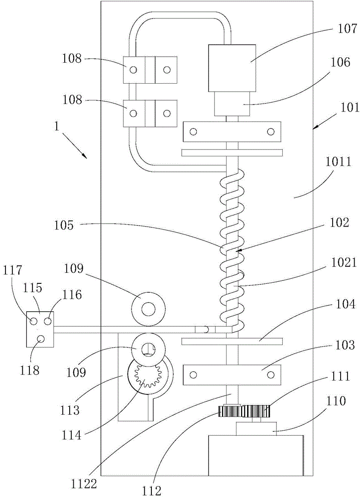
[0023] Such as figure 1 Shown are the preferred embodiments provided by the present invention.

[0024] The automatic charging pile 1 provided in this embodiment includes a box body 101, a sealed cavity 1011 is provided in the box body 101, and a rotating shaft 102 and two rotating seats 103 arranged in parallel and alternately arranged in the cavity 1011. The two ends of 102 are respectively rotatably inserted in the two rotating seats 103, and a winding section 102...


PUM


Abstract

The present invention relates to the field of charging piles and discloses an automatic charging pile which comprises a box body with a containing cavity which is internally provided with a rotation shaft, two rotation seats, a first solenoid valve which is connected to a power supply and a first motor. A winding section is formed between the two rotation seats by the rotation shaft, and one end of the rotation shaft is connected to the first motor through a first transmission structure. One end of an electric wire is connected to a second solenoid valve, and the other end extends out of the box body and is connected to a charging gun. A gap is arranged between the first solenoid valve and the second solenoid valve. The charging gun is provided with keys for controlling the first motor to rotate in forward and reverse directions and controlling the connection of the first solenoid valve and the second solenoid valve. According to the charging pile, through the keys on the charging gun, the connection of the first solenoid valve and the second solenoid valve is operated, the rotation of the first motor in the forward and reverse directions are controlled, the operation is simple, and the charging pile is convenient to use. The electric wire is arranged in the box body, electric wire aging or damage is avoided, an electric shock accident is avoided, and the safety performance is improved. The automatic operation is realized, a manual operation is avoided, and the efficiency is high.

Description

Technical field [0001] The invention relates to the technical field of charging piles, in particular to automatic charging piles. Background technique [0002] Charging pile refers to a special power supply device that provides AC power for electric vehicles with on-board charging first motor by means of conduction. Charging pile is a kind of charging and swapping facility for electric vehicles. Its maximum rated power is 7kW. It is mainly suitable for charging small passenger vehicles, such as pure electric vehicles or plug-in hybrid electric vehicles. It is fully charged according to the vehicle configuration battery capacity. The electricity time generally takes 3-8 hours. [0003] In the prior art, the charging pile includes a box body, in which electrical equipment, etc. are arranged, and the box body is provided with a charging interface, the charging interface is connected with a wire, and the outer end of the wire is connected with a charging gun. The electrical connectio...

Claims


Application Information

Patent Timeline
Patent Type & Authority Applications(China)
IPC IPC(8): H02J7/00
Inventor 陈汉良
Owner ARTOP DESIGN GRP CO LTD
Why Eureka
Try Eureka