Stator of a rotating electrical machine

A technology for rotating electrical machines and stators, which is applied in the manufacture of motor generators, electrical components, electromechanical devices, etc. It can solve the problems of coil cross-sectional area reduction, loss increase, coil eddy current loss, etc., and achieve the goal of suppressing the increase in resistance and suppressing manufacturing efficiency. The effect of reducing and suppressing the eddy current loss of the coil

Active Publication Date: 2018-04-20
HONDA MOTOR CO LTD
View PDF6 Cites 0 Cited by
  • Summary
  • Abstract
  • Description
  • Claims
  • Application Information

AI Technical Summary

Problems solved by technology

[0009] However, in the stator of the rotating electrical machine described in Patent Document 2, the space factor of the coils in the slots is increased by using slot coils, but in the case where cross magnetic flux (Japanese: cross magnetic flux) from the rotor side is generated The part of the coil in the slot may cause coil eddy current loss caused by leakage flux
[0010] On the other hand, in the stator of the rotating electric machine described in Patent Document 1, since one coil itself is composed of a plurality of conducting wires, even at the bridging portion other than the coil portion in the slot where the intersecting magnetic flux from the rotor side is generated, , the coil is also composed of a plurality of wires, so the cross-sectional area of ​​the coil is also reduced at the crossover part where the eddy current loss caused by the leakage magnetic flux is difficult to occur, thereby increasing the loss due to the increase of the resistance

Method used


Image

  • Stator of a rotating electrical machine
  • Stator of a rotating electrical machine
  • Stator of a rotating electrical machine

Examples


Embodiment Construction

[0095] Hereinafter, one Embodiment of the stator of the rotating electrical machine of this invention is demonstrated based on drawing. It should be noted that the drawings are viewed according to the orientation of the symbols.

[0096] [stator]

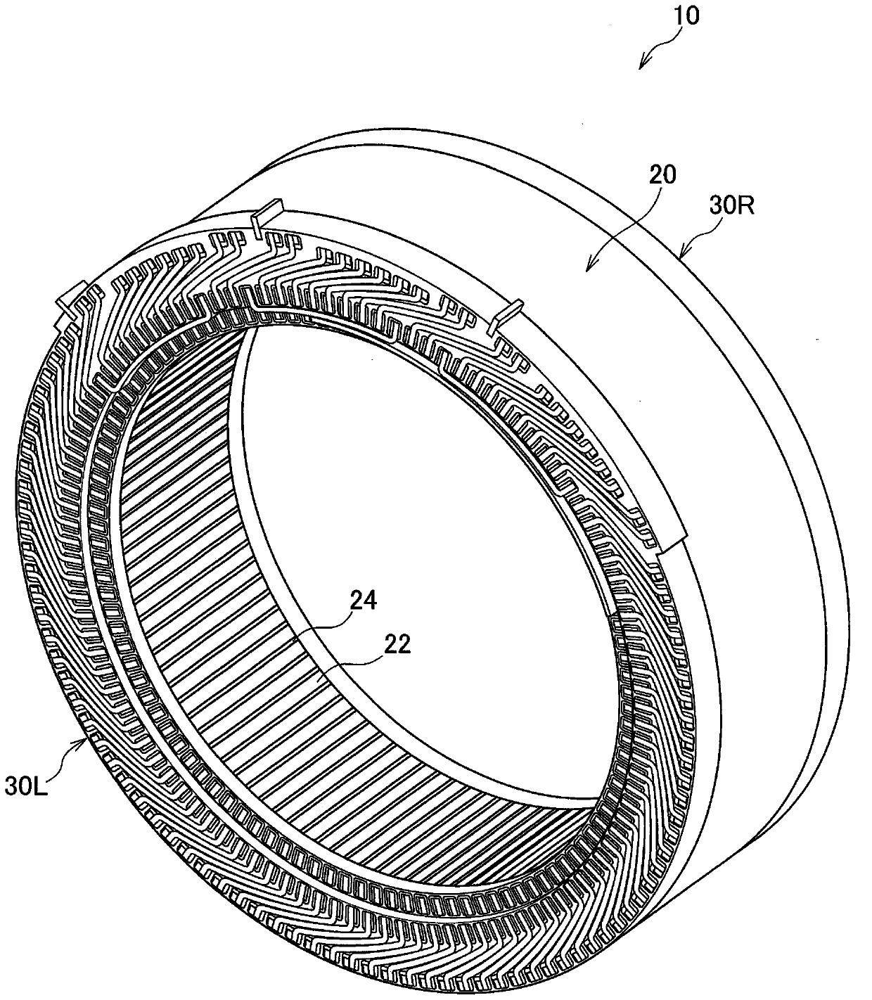
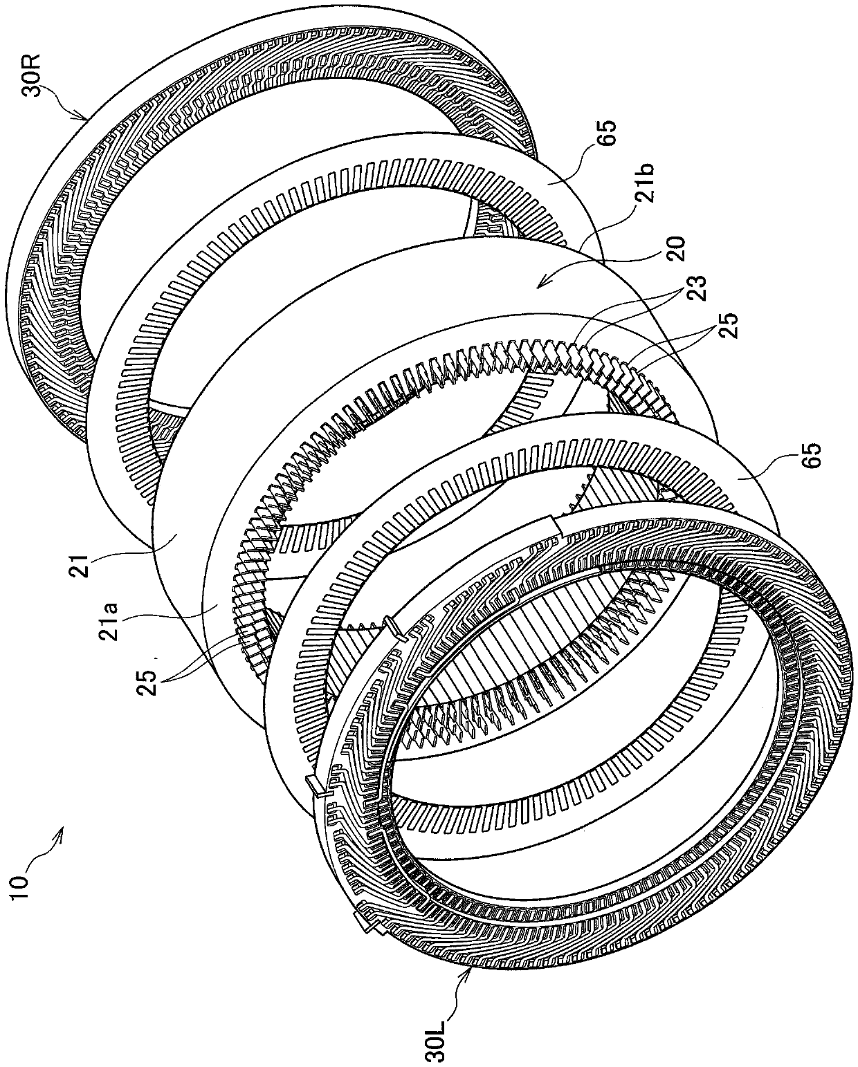
[0097] like figure 1 and figure 2 As shown, the stator 10 of the rotating electrical machine according to the present embodiment includes a stator core assembly 20 and a pair of substrate assemblies 30L and 30R. The substrate assemblies 30L and 30R are arranged and assembled on both sides of the stator core assembly 20 . An insulating sheet 65 such as a silicon wafer is disposed between the stator core assembly 20 and the board assemblies 30L and 30R, and insulates the stator core assembly 20 and the board assemblies 30L and 30R.

[0098] [1 stator core assembly]

[0099] The stator core assembly 20 includes a stator core 21 and a plurality of (108 in the illustrated embodiment) slot coils 25 .

[0100] [1-1 stator core]

[0...


PUM


Abstract

The present invention provides a stator of a rotating electrical machine capable of suppressing coil eddy current loss and securing a cross-sectional area of ​​a bridge portion. A stator (10) of a rotating electric machine constitutes a coil (50) by combining slot coils (25) and connecting coils (40) which are in contact with each other. A slit (27d) is formed in a portion of the slot coil (25) located in the slot (21), and the slit (27d) penetrates the slot coil (25) and extends from one end side toward the other end side in the axial direction.

Description

technical field [0001] The present invention relates to a stator of a rotating electric machine that can be mounted on an electric vehicle, a hybrid vehicle, or the like. Background technique [0002] Conventionally, there has been known a stator for a rotating electric machine in which coils are formed by winding windings around teeth of a stator core. For example, Patent Document 1 describes a stator for a rotating electrical machine in which one coil itself is composed of a plurality of conducting wires in order to increase the space factor of windings inserted into slots and suppress the generation of eddy currents. [0003] In addition, in recent years, as a stator for other rotating electrical machines, a rotating electrical machine using segmented coils has been proposed. For example, in Patent Document 2, a coil loop is formed by tightly coupling a slot coil arranged in a slot of a stator core and a connection coil arranged outside the stator core as a jumper. [0...

Claims


Application Information

Patent Timeline
Patent Type & Authority Patents(China)
IPC IPC(8): H02K1/16
CPCH02K3/28H02K3/50H02K2213/03H02K3/12H02K15/0025H02K3/24H02K3/18H02K3/345H02K3/32H02K3/04H02K3/34
Inventor 高桥忠伸壹岐友贵永广健太郎
Owner HONDA MOTOR CO LTD
Why Eureka
Try Eureka