The method of configuring the aggregated maximum rate of ue, coordinating the aggregated rate of non-gbr services and the base station
A technology that aggregates the maximum rate and UE-AMBR, which is applied in the direction of digital transmission system, network traffic/resource management, electrical components, etc., can solve the problem of no involvement, and achieve the effect of reducing data transmission delay and effectively utilizing data bearing bandwidth
- Summary
- Abstract
- Description
- Claims
- Application Information
AI Technical Summary
Problems solved by technology
Method used
Image
Examples
Embodiment 1
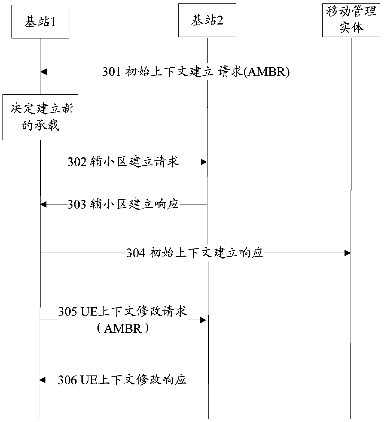
[0049] This embodiment describes the process in which base station 1 establishes a user data bearer on base station 2, MME sets the aggregate maximum rate of UE for the base station, and configures the maximum aggregate rate of UE through the X2 interface between base stations, as shown in image 3 shown. Among them: base station 1 is the base station where the user's serving cell is located, that is, the base station MeNB where the user's main cell is located, base station 2 is SeNB, which provides data bearer for the user, base station 2 receives downlink data from the serving gateway or base station 1 and sends it to the UE, base station 1 There is an X2 interface with base station 2. This embodiment omits the signaling interaction process between the base station and the UE, and between the MME and the gateway. image 3 The illustrated process may include the following steps:
[0050] Step 301: MME sends an "initial context establishment request" message to base station ...
Embodiment 2
[0075]This embodiment describes a method for base station 1 and base station 2 to coordinate and adjust the aggregation rate. The base station 1 is the base station MeNB where the serving cell of the user is located, and the base station 2 is the SeNB that provides data bearer for the user. Base station 2 receives downlink data from the gateway or base station 1 and sends it to the UE. There is an X2 interface between base station 1 and base station 2. In this embodiment, the process of signaling interaction between the base station and the UE, and between the MME and the gateway is omitted.
[0076] This embodiment provides two different implementation methods, respectively as Figure 4 Method 1 and Method 2 in the above.
[0077] Figure 4 The shown method one may include the following steps:
[0078] Step 401a: Base station 2 sends an "aggregation rate report" message to base station 1.
[0079] In this message, the identification information of the UE on the X2 interf...
Embodiment 3
[0104] This embodiment describes that the main base station MeNB determines the AMBR used by the MeNB and the SeNB according to the QCI. Figure 5 The shown method may include the following situations. In the following description, base station 1 may be a MeNB and base station 2 may be an SeNB; or base station 1 may be a SeNB and base station 2 may be a MeNB.
[0105] 1. Allocate the same QCI to the non-GBR on the MeNB and the SeNB. At this time, the MeNB allocates the same AMBR to the MeNB and the SeNB, and the sum of the two AMBRs is equal to the UE-ABMR. For example, if UE-AMBR=100, then the AMBRs of MeNB and SeNB are 50 respectively.
[0106] 2. The QCI of the non-GBR bearer established on base station 1 is 5, and the QCI of the non-GBR bearer established on base station 2 is 7. At this time, MeNB allocates the same AMBR to base station 1 and base station 2, the sum of the two AMBRs Equal to UE-ABMR. For example, if UE-AMBR=100, then the AMBRs of MeNB and SeNB are 50 res...
PUM
 Abstract
Description
Claims
Application Information
 - R&D
- Intellectual Property
- Life Sciences
- Materials
- Tech Scout
- Unparalleled Data Quality
- Higher Quality Content
- 60% Fewer Hallucinations
Browse by: Latest US Patents, China's latest patents, Technical Efficacy Thesaurus, Application Domain, Technology Topic, Popular Technical Reports.
© 2025 PatSnap. All rights reserved.Legal|Privacy policy|Modern Slavery Act Transparency Statement|Sitemap|About US| Contact US: help@patsnap.com


