Dual wedge clamp angled blade cutter system

A technology of blade and cutting head, applied in the field of blade assembly, which can solve the problems of high risk and tedious labor intensity of operators

Active Publication Date: 2015-09-30
GRACO INC
View PDF6 Cites 2 Cited by
  • Summary
  • Abstract
  • Description
  • Claims
  • Application Information

AI Technical Summary

Problems solved by technology

This technique is tedious and labor intensive and presents a higher risk to the operator due to the need to manipulate each blade when removing the old blade and inserting the new blade into the blade wheel

Method used


Image

  • Dual wedge clamp angled blade cutter system
  • Dual wedge clamp angled blade cutter system
  • Dual wedge clamp angled blade cutter system

Examples


Embodiment Construction

[0020] This application claims a U.S. provisional application filed January 31, 2013 by inventors Todd Domer, Paul Jones, Jonathan McMichael and Daniel Chase Priority of Serial No. 61 / 759,043, the contents of which are hereby incorporated by reference.

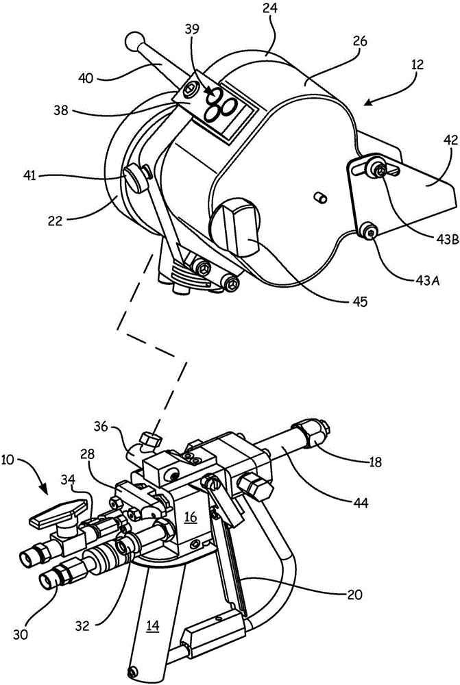
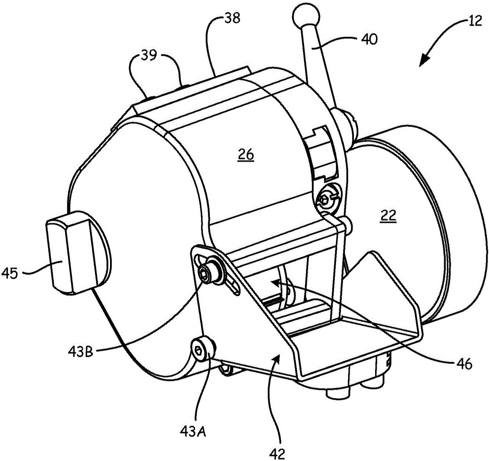
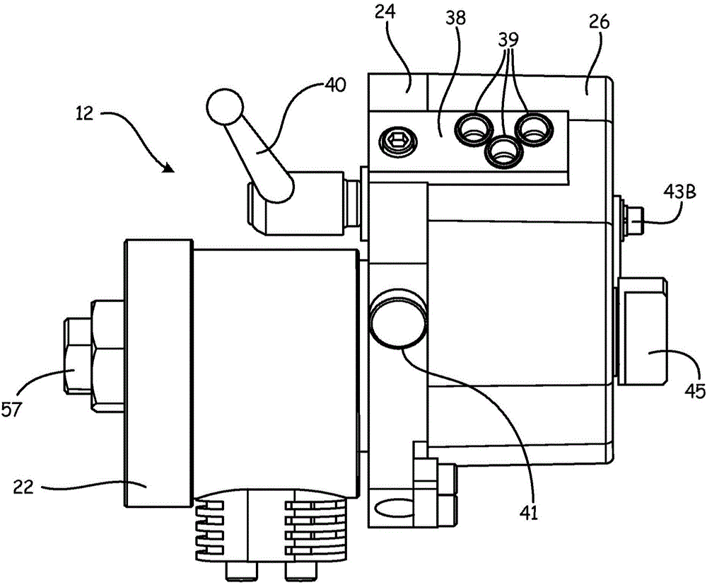
[0021] figure 1 is an exploded view of the assembly of a liquid spray gun 10 and a fiber roving chopper 12 utilizing the cutting head assembly of the present invention. exist figure 1 , the fiber roving chopper 12 is shown slightly enlarged relative to the liquid spray gun 10 . The liquid spray gun 10 includes a two-component internal mixing gun having a handle 14 , a valve body 16 , a nozzle 18 and a trigger 20 . The fiber roving chopper 12 includes an air motor 22 , a housing 24 and a cover 26 . Valve body 16 of spray gun 10 includes valve assembly 28 , air inlet 30 , material inlet 32 ​​, catalyst inlet 34 and air outlet 36 . Housing 24 of fiber roving chopper 12 includes fiber inlet 38 , opening 39 , lever 40 , knob 4...


PUM


Abstract

A cutter head assembly for a fiber roving chopper includes a cylindrical blade cartridge extending axially between a cartridge first end and a cartridge second end. The cylindrical blade cartridge includes a first surface that extends between the cartridge first and second ends and is angled with respect to a central axis of the cylindrical blade cartridge. A second surface extends between the cartridge first and second ends parallel to the first surface and the second surface faces the first surface. A blade body extends between the cartridge first end and the cartridge second end and is disposed between the first surface and the second surface.

Description

field of invention [0001] The present invention generally relates to a shredder arrangement for distributing fibrous material into a flow of resin material dispensed by a spray gun. More specifically, the present invention relates to a blade assembly for use in a shredder device. Background technique [0002] Shredder guns are frequently used in the composites industry to form large, shaped products such as in the marine and marine industry and the swimming pool and spa industry. The shredder gun includes an assembly of a fiber shredder and a liquid spray gun. Typically compressed air may be supplied by a pumping mechanism to an external pump and to the air motor in the fiber chopper. A pumping mechanism typically delivers liquid resin material and liquid catalyst material to the spray gun. Actuation of a trigger on the spray gun dispenses material into the mixing chamber before being sprayed out of the nozzle of the spray gun. The mixing of the catalyst and resin starts...

Claims


Application Information

Patent Timeline
Patent Type & Authority Applications(China)
IPC IPC(8): B02C18/18B26D1/36B26D1/62
CPCB29B7/885B05B7/0408B29B7/7447B26D1/40B29B7/90B29B7/7452B05B7/1422B26D1/365B26D1/62B02C18/18
Inventor 托德·A·多默保罗·M·琼斯乔纳森·R·MC迈克尔丹尼尔·J·蔡斯
Owner GRACO INC
Why Eureka
Try Eureka