
a deflation device

A technology of air release device and air release screw, which is applied to parts of pumping devices for elastic fluids, parts of variable displacement pumps, machines/engines, etc. and other problems, to achieve the effect of simple structure, long service life and good structural stability

Active Publication Date: 2017-08-15
ZHEJIANG ZHUJI WANBAO MASCH CO TLD
View PDF7 Cites 0 Cited by
  • Summary
  • Abstract
  • Description
  • Claims
  • Application Information

AI Technical Summary

Problems solved by technology

[0003] The technical problem to be solved by the present invention is to solve the deficiencies in the prior art that the horizontal through hole on the venting screw is subjected to axial force, improper force during maintenance or use, causing extrusion deformation, channel blockage, and affecting the exhaust effect.

Method used


Image

  • a deflation device
  • a deflation device
  • a deflation device

Examples


Embodiment Construction

[0019] In order to make the objectives, technical solutions and advantages of the present invention clearer, the present invention will be further described in detail below with reference to the accompanying drawings and embodiments. It should be understood that the specific embodiments described herein are only used to explain the present invention, but not to limit the present invention.

[0020] In the description of the present invention, it should be understood that the orientations or positional relationships indicated by the terms "upper", "lower", "front", "rear", "inner", "outer", etc. are based on those shown in the accompanying drawings The orientation or positional relationship is only for the convenience of describing the present invention and simplifying the description, rather than indicating or implying that the indicated device or element must have a specific orientation, be constructed and operated in a specific orientation, and therefore should not be constru...


PUM


Abstract

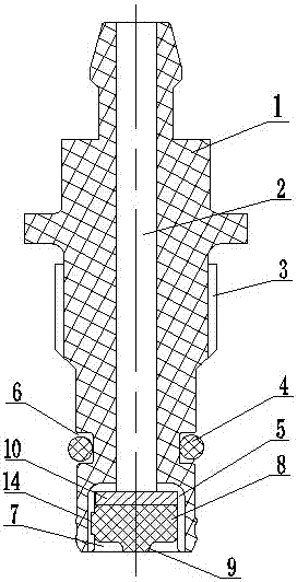
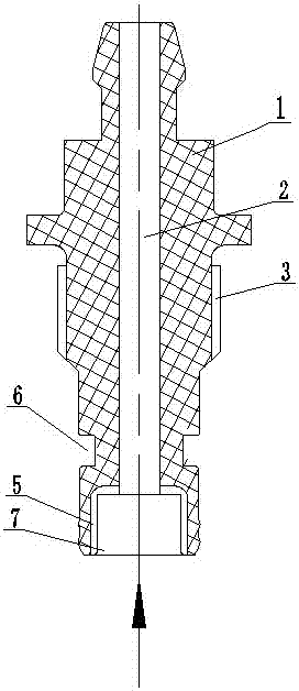
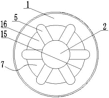
The invention relates to an air bleeding device which can be used for the exhaust of a hydraulic pipe-line system. The air bleeding device includes an air-bleed screw (1), outer threads (3) are arranged on the air-bleed screw, an exhaust vent (2) is arranged inside the air-bleed screw, the lower end of the air-bleed screw is provided with a sink hole (7) which is communicated with the exhaust vent, the diameter of the sink hole is greater than that of the exhaust vent, the inner wall (15) and the hole bottom surface (16) of the sink hole are provided with a plurality of ventilation grooves (5), and the ventilation grooves are communicated with the exhaust vent from the end face of the lower end of the air-bleed screw via the inner wall and the hole bottom surface of the sink hole. The air bleeding device further includes a sealing member (8) arranged in the sink hole, and the sealing member is in interference fit with the sink hole. The air bleeding device is simple in structure, the ventilation grooves are good in structure stability and are not easy to deform under normal pressure, and the service life of the air bleeding device is prolonged.

Description

technical field [0001] The invention relates to an air release device, which is applied to the air release of a hydraulic pipeline system. Background technique [0002] At present, the hydraulic pipeline bleed structure in the industry adopts metal machined parts, and the bleed bolt and the body achieve the sealing effect through rigid interference fit. This structure requires high machining accuracy, and is based on the linear interference fit between the related parts. It is sealed, and there is a horizontal through hole on the vent screw, which is easy to cause extrusion deformation, channel blockage, and affect the exhaust effect during axial force, maintenance or use. SUMMARY OF THE INVENTION [0003] The technical problem to be solved by the present invention is to solve the defects in the prior art that the transverse through hole on the air vent screw is easily subjected to axial force, improper force during maintenance or use, resulting in extrusion deformation, c...

Claims


Application Information

Patent Timeline
Patent Type & Authority Patents(China)
IPC IPC(8): F04B53/06
Inventor 边届吴超华
Owner ZHEJIANG ZHUJI WANBAO MASCH CO TLD
Learn More