Efficient and energy-saving three-dimensional-flow multi-stage centrifugal blower

A centrifugal blower, high-efficiency and energy-saving technology, applied in the direction of pump components, mechanical equipment, radial flow pumps, etc., can solve the problems of sound insulation cover loss, high noise, large cooling water volume, etc., to reduce frequency and cost, reduce noise and energy Consumption, the effect of improving work efficiency

Inactive Publication Date: 2015-10-07
JIANGSU LAISEN ENVIRONMENTAL PROTECTION EQUIP CO LTD
View PDF10 Cites 2 Cited by
  • Summary
  • Abstract
  • Description
  • Claims
  • Application Information

AI Technical Summary

Problems solved by technology

[0005] This blower is the most traditional fan. Advantages: low price, easy installation and operation; Disadvantages: loud noise, low efficiency, high maintenance frequency
[0007] This blower was born instead of the Roots blower in the 1980s. Advantages: moderate price, easy installation and operation, low noise, low maintenance frequency, and strong adjustability; Disadvantages: Although the efficiency is higher than the Roots blower, it is still only about 70%.
[0009] Advantages: the blower itself has high efficiency, simple installation, and strong adjustability; Disadvantages: high price, relatively complicated operation, high noise and must be equipped with a sound insulation cover, large cooling water, gear box loss efficiency, sound insulation cover loss efficiency, maintenance frequency Higher, higher maintenance costs
[0011] Advantages: high blower efficiency, low noise, easy installation, strong adjustability, small footprint; Disadvantages: relatively complicated operation, high maintenance frequency, high maintenance cost, no high-power models

Method used


Image

  • Efficient and energy-saving three-dimensional-flow multi-stage centrifugal blower
  • Efficient and energy-saving three-dimensional-flow multi-stage centrifugal blower
  • Efficient and energy-saving three-dimensional-flow multi-stage centrifugal blower

Examples


Embodiment Construction

[0025] The preferred embodiments of the present invention will be described in detail below in conjunction with the accompanying drawings, so that the advantages and features of the present invention can be more easily understood by those skilled in the art, so as to define the protection scope of the present invention more clearly.

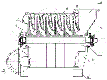
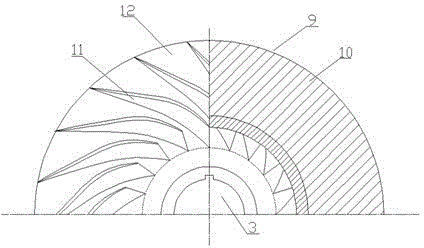
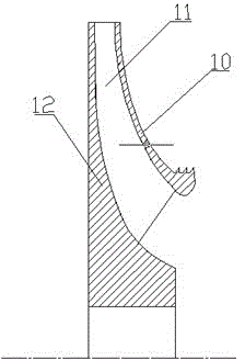
[0026] Such as figure 1 , figure 2 with image 3 A high-efficiency and energy-saving ternary flow multi-stage centrifugal blower shown includes a casing 1, an impeller group 2 and a main shaft 3, the casing 1 adopts a vertical cover, and the casing 1 includes a front baffle 4, a rear baffle plate 5 and an integrated partition 6, the front baffle 4 and the rear baffle 5 are respectively arranged at both ends of the integrated partition 6, a cooling water chamber 7 is arranged inside the integrated partition 6, and the integrated A partition chamber 8 is formed in the middle of the partition plate 6, the impeller group 2 is arranged in the parti...


PUM


Abstract

The invention relates to an efficient and energy-saving three-dimensional-flow multi-stage centrifugal blower which comprises a blower shell, an impeller set and a main shaft. A vertically-sealed face is adopted by the blower shell. The blower shell comprises a front baffle, a rear baffle and an integrated partition disc. The front baffle and the rear baffle are arranged at the two ends of the integrated partition disc. A cooling water cavity is formed in the integrated partition disc. A partition disc chamber is formed in the middle of the integrated partition disc. The impeller set is arranged in the partition disc chamber. The main shaft penetrates through the two ends of the blower shell and is arranged in the middle of the blower shell. The impeller set is arranged on the main shaft and comprises a plurality of impellers. Each impeller comprises a front wheel disc, a blade and a rear wheel disc. The blades are arranged on the rear wheel discs respectively. The front wheel discs are arranged on the front sides of the blades respectively. Each blade is a three-dimensional blade. According to the efficient and energy-saving three-dimensional-flow multi-stage centrifugal blower, because the three-dimensional-flow impellers, the blower shell with the vertically-sealed face and the integrated partition disc are adopted, the blower can operate more stably, efficiency is improved, energy consumption is lowered, and the service life is prolonged.

Description

technical field [0001] The invention relates to a high-efficiency and energy-saving ternary flow multistage centrifugal blower. Background technique [0002] my country's fan industry has a long history of development. Fans have made great contributions to the growth of my country's national economy. Especially when my country has entered the era of environmental protection, low-flow high-pressure blowers have been widely used as heart equipment for deepening aeration in sewage treatment plants and desulfurization and oxidation processes in power plants. Applications. With the rapid growth of my country's economy, especially after entering the "Twelfth Five-Year Plan", the country has increased investment in infrastructure construction, and environmental protection equipment has become a pillar industry for my country's national economic growth, which will inevitably stimulate small flow and high pressure blowers. The market is more prosperous. Since the energy consumption of...

Claims


Application Information

Patent Timeline
Patent Type & Authority Applications(China)
IPC IPC(8): F04D17/12F04D29/02F04D29/28F04D29/66
Inventor 宋果文韩斌
Owner JIANGSU LAISEN ENVIRONMENTAL PROTECTION EQUIP CO LTD
Why Eureka
Try Eureka