
Omnidirectional photocatalyst super-power LED lamp

A super-high-power, LED lamp technology, applied in the field of lamps and lanterns, can solve the problems of low sterilization efficiency, long start-up time, and the need for a dedicated power supply, etc., to achieve good cooling and heat dissipation effects, wide irradiation angle, and increased cooling and heat dissipation space.

Active Publication Date: 2015-10-07
徐虹
View PDF5 Cites 6 Cited by
  • Summary
  • Abstract
  • Description
  • Claims
  • Application Information

AI Technical Summary

Problems solved by technology

Taking ultraviolet radiation as an example, the traditional sterilization and disinfection functions are usually realized by the ultraviolet rays emitted by low-pressure mercury vapor lamps. Low-pressure mercury vapor lamps have high energy consumption, short life, large volume, easy damage, special power supply, and long startup time. And many other shortcomings, its application is mainly limited to the medical field, it is difficult to be widely used in more fields, and the mercury content in the lamp is easy to cause environmental pollution
[0003] At present, there are LED disinfection lamps with low power, small irradiation angle, and low sterilization efficiency. They are not suitable for large-scale disinfection, and they are often only suitable for air disinfection, not water disinfection.

Method used


Image

  • Omnidirectional photocatalyst super-power LED lamp
  • Omnidirectional photocatalyst super-power LED lamp
  • Omnidirectional photocatalyst super-power LED lamp

Examples


Embodiment 1

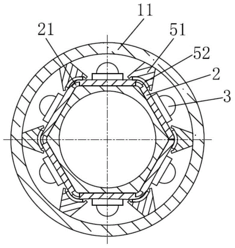
[0032] like figure 1 As shown, the present invention discloses a full-angle photocatalyst ultra-high-power LED lamp, which includes a lamp body, a light source substrate 2, an LED light source body 3, a drive assembly 6 and a lamp head assembly, wherein:

[0033] The lamp body includes a lampshade pipe 11 and a support pipe 12 disposed in the lampshade pipe 11 . The lampshade tube 11 is a glass lampshade tube 11, and the outer wall of the lampshade tube 11 is coated with a nanometer photocatalyst coating 111, which produces sterilization and disinfection ability after being excited by light.

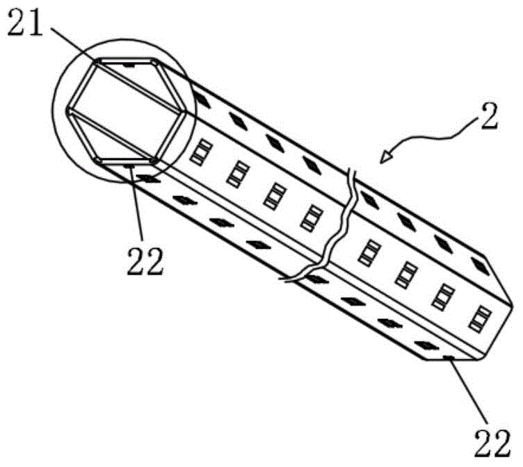
[0034] like Figure 1-3 As shown, the light source substrate 2 is arranged in the lampshade tube 11, and the light source substrate 2 is bent to form a mounting surface of the LED light source body 3 with a polygonal cross section. The LED light source body 3 is installed on the light source substrate 2 and has a wide irradiation angle. The support tube 12 is a polygonal profile attach...

Embodiment 2

[0042] Such as Figure 6 , Figure 7 As shown, the differences between this embodiment and Embodiment 1 are:

[0043] The structure of the lamp head assembly is different and the position of the drive assembly 6 is different.

[0044] Specifically, the driving assembly 6 is arranged inside the support tube 12, and the lamp assembly includes a waterproof outlet lamp holder 71 and a blind end lamp holder 72 respectively arranged at both ends of the lampshade tube 11. The waterproof outlet lamp holder 71 is provided with an outlet hole 714, and the wire 73 of the drive assembly 6 passes through The outlet hole 714 is connected with an external power source.

[0045] The waterproof outlet lamp holder 71 includes an inner connector 711, a tapered sealing rubber sleeve 712 and a nut screw cover 713. The inner connector 711 and the lampshade tube 11 are sealed and connected by an O-ring 7112. The inner connector 711 and the blind end lamp holder 72 are equipped with The second hoo...

Embodiment 3

[0048] Such as Figure 8 As shown, the differences between this embodiment and Embodiment 1 are:

[0049] The structure of the lamp head assembly is different and the position of the drive assembly 6 is different.

[0050] The driving assembly 6 is arranged inside the support tube 12. The lamp cap assembly includes a power connection lamp cap 81 and an insulating lamp cap 82 respectively arranged at both ends of the lampshade tube 11. Both the power connection lamp cap 81 and the insulating lamp cap 82 are provided with a third buckle 812. The light source substrate 2 is provided with There is a fastening hole 22 matching with the third clasp 812 ; the power connection lamp cap 81 is provided with conduction pins 811 , and the insulating lamp cap 82 is provided with insulating pins 821 . The power connection lamp holder 81 and the insulating lamp holder 82 adopt the standard of the traditional fluorescent lamp holder.

[0051] The LED lamp of this embodiment is air-cooled on...


PUM


Abstract

The invention discloses an omnidirectional photocatalyst super-power LED lamp which comprises a lamp tube body, a light source substrate, LED light source bodies, a driving assembly and a lamp holder assembly. The lamp tube body comprises a lampshade tube and a bearing tube located in the lampshade tube. The outer wall of the lampshade tube is coated with a nano photocatalyst coating, and the lamp holder assembly is arranged at the ends of the bearing tube and the ends of the lampshade tube. The light source substrate is arranged in the lampshade tube, and the light source substrate is bent to form an LED light source body mounting face with a polygonal cross section. The bearing tube is a polygonal section attached to the inner face of the light source substrate. The LED light source bodies are arranged on the light source substrate. The driving assembly is electrically connected with the LED light source bodies. The LED lamp is mainly applied to water and air environmental space sterilization and disinfection occasions. The LED lamp has the advantages of being super in power, high in illuminance and high in efficiency, the sterilization and disinfection treatment capacity is improved, and the LED lamp can be widely applied to water treatment and air space sterilization and disinfection products.

Description

technical field [0001] The invention relates to a lamp, in particular to an all-angle photocatalyst super-high-power LED lamp. Background technique [0002] Ozone, ultraviolet radiation, chemical drug fumigation, spraying and other methods are often used for disinfection and sterilization of water and air, but these methods all have many defects in use. Taking ultraviolet radiation as an example, the traditional sterilization and disinfection functions are usually realized by the ultraviolet rays emitted by low-pressure mercury vapor lamps. Low-pressure mercury vapor lamps have high energy consumption, short life, large volume, easy damage, special power supply, and long startup time. And many other shortcomings, its application is mainly limited to the medical field, it is difficult to be widely used in more fields, and the mercury content in the lamp is easy to cause environmental pollution. [0003] At present, there are LED disinfection lamps, which have low power, smal...

Claims


Application Information

Patent Timeline
IPC IPC(8): F21S2/00F21V19/00F21V29/70B01D53/86C02F1/30A61L9/18F21Y101/02
CPCA61L9/18B01D53/86C02F1/30F21V19/001
Inventor 徐虹
Owner 徐虹
Learn More