Lamp high in cooling efficiency and good in safety performance

A technology with safety performance and heat dissipation efficiency, applied in the safety devices of lighting devices, lighting and heating equipment, cooling/heating devices of lighting devices, etc. Low and other problems, to achieve the effect of high heat dissipation performance and thermal conductivity, good thermal conductivity and heat dissipation performance, and ensuring personal safety

Inactive Publication Date: 2015-10-07
陈美霞
View PDF3 Cites 0 Cited by
  • Summary
  • Abstract
  • Description
  • Claims
  • Application Information

AI Technical Summary

Problems solved by technology

[0002] Lamps are indispensable electrical appliances in people's daily work and life. Existing lamps generally include a lamp cap nut, a lamp holder connected and fixed on the upper end of the lamp cap nut, an illuminant structure fixed on the upper end of the lamp holder, and a lamp holder. Connect and fix the light-transmitting cover outside the illuminant structure. The illuminant structure generates a lot of heat, and generally there are problems affecting its normal operation and service life due to poor heat dissipation.
On the other hand, due to safety considerations, designers are worried about electric shock accidents. Existing lamp holders are generally made of insulating materials such as plastics, but the thermal conductivity and heat dissipation performance of plastics are poor, and the heat dissipation efficiency is low, which is not conducive to heat dissipation. Conduction and dissipation, after long-term work, it is easy to cause heat accumulation in the structure of the luminous body. If the temperature is too high, it will easily affect its working effect and service life

Method used


Image

  • Lamp high in cooling efficiency and good in safety performance

Examples


Embodiment Construction

[0011] It should be understood that the specific embodiments described here are only used to explain the present invention, not to limit the present invention.

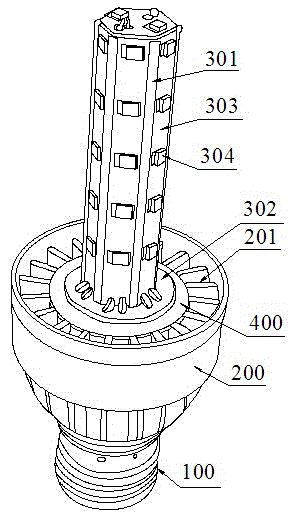
[0012] refer to figure 1 , an embodiment of a lamp with high heat dissipation efficiency and good safety performance of the present invention is proposed, which includes a lamp cap nut 100, a lamp holder 200 connected and fixed on the upper end of the lamp cap nut 100 with a hollow cavity inside, and fixed on The illuminant structure at the upper end of the lamp holder 200 , the light-transmitting cover that is fixedly connected with the lamp holder 200 and covered outside the illuminant structure, also includes a driving device accommodated in the hollow cavity.

[0013] The illuminant structure includes a light source installation column 301 fixed on the upper end of the lamp holder 200, an LED light source structure closely attached to the side and top surface of the light source installation column 301, and an ele...


PUM


Abstract

The invention discloses a lamp high in cooling efficiency and good in safety performance. The lamp comprises a lamp cap nut, a lamp holder with a hollow cavity inside, a light emitting body structure, a light-pervious cover and a drive device. The light emitting body structure comprises a light source installation column fixedly arranged at the upper end of the lamp holder, an LED light source structure and a main substrate arranged at the lower end of the light source installation column in an enclosing mode and electrically connected with the LED light source structure. The LED light source structure comprises light source substrates and LED lamp beads, the light source substrates are attached to the side face and the top face of the light source installation column, and the LED lamp beads are distributed on the light source substrates. Multiple longitudinal ribs are annularly distributed between the outer side wall of the lamp holder and the hollow cavity, and longitudinal ventilation cooling holes can be formed through the longitudinal ribs. Grooves are formed between the upper ends of the longitudinal ribs and the upper end face of the hollow cavity. A ceramic isolation piece made of ceramics is embedded in the grooves, is located between the lamp holder and the light emitting body structure and has the insulating function and the heat transferring and dissipating function. The lamp holder and the light source installation column are both of an integrally formed structure and made of aluminum.

Description

technical field [0001] The invention relates to the technical field of lamps, in particular to a lamp with high heat dissipation efficiency and good safety performance. Background technique [0002] Lamps are indispensable electrical appliances in people's daily work and life. Existing lamps generally include a lamp cap nut, a lamp holder connected and fixed on the upper end of the lamp cap nut, an illuminant structure fixed on the upper end of the lamp holder, and a lamp holder. The light-transmitting cover that is connected and fixed and placed outside the illuminant structure, the illuminant structure generates a large amount of heat, generally has the problem of affecting its normal operation and service life due to poor heat dissipation. On the other hand, due to safety considerations, designers are worried about electric shock accidents. Existing lamp holders are generally made of insulating materials such as plastics, but the thermal conductivity and heat dissipation ...

Claims


Application Information

Patent Timeline
Patent Type & Authority Applications(China)
IPC IPC(8): F21S2/00F21V29/83F21V29/89F21V29/85F21V29/77F21V25/00F21Y111/00
CPCF21V25/00
Inventor 李铎方
Owner 陈美霞
Why Eureka
Try Eureka