
Chilled water storage device

A technology of water storage and cold storage, applied in heating methods, lighting and heating equipment, applications, etc., can solve the problems of difficult operation control, low space utilization rate, and high membrane requirements, so as to reduce invalid space, increase water storage temperature difference, Effect of increasing cold storage density

Inactive Publication Date: 2015-10-07
GUANGZHOU INST OF ENERGY CONVERSION - CHINESE ACAD OF SCI
View PDF7 Cites 4 Cited by
  • Summary
  • Abstract
  • Description
  • Claims
  • Application Information

AI Technical Summary

Problems solved by technology

In the double-slot type, there is always one tank that cannot be used, and the space utilization rate is low; the operation of the multi-slot system requires multiple valves to switch, the system is complex, and the operation control is difficult; the labyrinth water flow rate is not easy to control, and it is easy to form a vortex or a short circuit to cause dead In addition, there are some disadvantages such as mixing of cold and warm water and large water resistance; the diaphragm in the single-slot diaphragm type is continuously pulled up and down, which has high requirements for the membrane and low practicability; The density of water is the highest at 4°C, and the phenomenon of "lower cooling and upper heating" without stirring is used to carry out natural temperature stratified cold storage, but precise design and construction are required to ensure that the thickness of the thermocline layer is as small as possible. In order to improve the efficiency of cold storage, and the lowest cold storage temperature is not less than 4°C

Method used


Image

  • Chilled water storage device
  • Chilled water storage device
  • Chilled water storage device

Examples


Embodiment Construction

[0019] The present invention will be further described below in combination with specific embodiments.

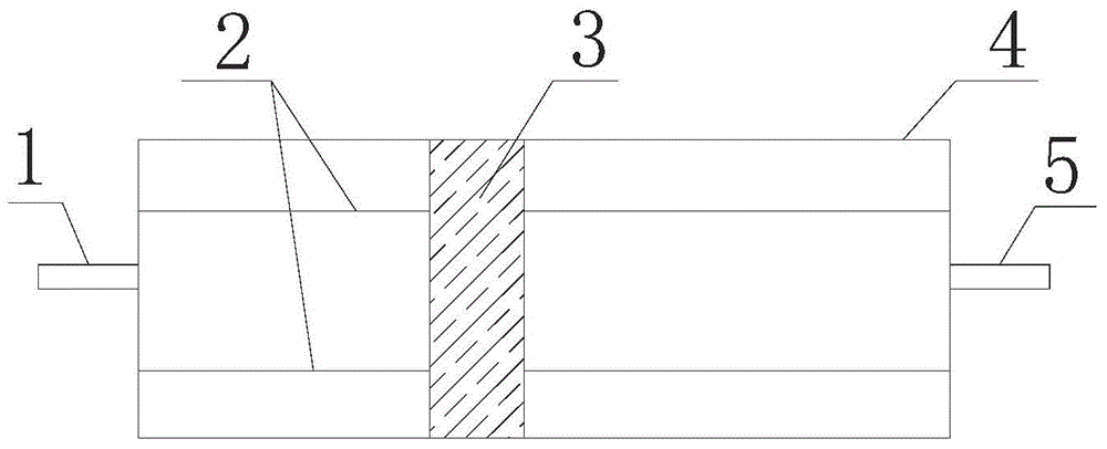
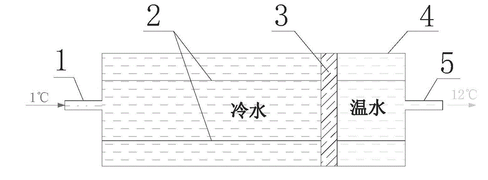
[0020] The water cold storage device of the present invention, such as figure 1 As shown, it includes cold storage water inlet / cooling water outlet 1, guide slide bar 2, partition plate 3, cold storage container 4 and cold storage water outlet / cooling water inlet 5.

[0021] The cold storage container 4 is a closed structure, the guide slider 2 is fixed in the cold storage container 4, the partition plate 3 is set on the guide slider 2, and can slide along the guide slider 2, and the cold storage container 4 is divided into two completely isolated parts , one side stores cold water, one side stores warm water, a cold storage water inlet / cooling water outlet 1 is set on the container wall on the cold water side, and a cold storage water outlet / cooling water inlet 5 is set on the container wall on the warm water side.

[0022] The cold storage water inlet / cooling outlet 1 is...


PUM


Abstract

The invention discloses a chilled water storage device comprising a chill storage water inlet / chill discharge water outlet, a guiding slide bar, a separating plate, a chill storage container, and chill storage water outlet / chill discharge water inlet. The chill storage container is an closed structure, the guiding slide bar is fixed in the chill storage container, the separating plate sleeves on the guiding slide bar and can slide along the guiding slide bar to separate the chill storage container into two totally isolated portions which are a chilled water storage portion and a warm water storage portion, the wall, at the cool water side, of the container is provided with the chill storage water inlet / chill discharge water outlet, and the wall, at the warm water side, of the container is provided with the chill storage water outlet / chill discharge water inlet. When chill is stored / discharged, the separating plate slides along the slide bar under the function of pressure difference of a circulating water pump, thermal stratification occurs in a common chilled water storage device can be eliminated, chilled water storage devices can be used in parallel in conditions with different capacities because of the closed structure, and the chilled water storage device also can be made into different shapes and sizes to be freely assembled on site, so the chilled water storage device is high in space utilization rate, good in place adaptability and capacity adaptability and high in storage and chilling efficiency.

Description

technical field [0001] The invention relates to the technical field of refrigeration and heating, in particular to a water cold storage device. Background technique [0002] Water storage air-conditioning technology is a technology that uses sensible heat of water to store cold energy: it is made of refrigeration equipment during the time period when no cooling capacity is needed or less cooling capacity is needed (when the power grid is at a low point at night, and the air-conditioning load is also low at the same time). The low-temperature water is stored and then used during the peak period of air-conditioning or process cooling (when the power grid peaks during the day, it is usually also the peak of the air-conditioning load) to meet the demand. As an effective way to shift peaks and fill valleys of electric power, it can achieve the effect of economical operation, energy saving and environmental protection, and has been widely used. However, in practical applications, ...

Claims


Application Information

Patent Timeline
IPC IPC(8): F24F5/00
CPCF24F5/0017F24F2005/0025Y02E60/14
Inventor 胡涛管海凤董凯军陈照杰
Owner GUANGZHOU INST OF ENERGY CONVERSION - CHINESE ACAD OF SCI
Learn More