High-precision and wide-current-range current mirror

A technology of current range and current mirror, which is applied in the field of current mirror to achieve the effect of improving the accuracy of current mirroring, improving the accuracy of voltage, and widening the range of current mirroring

Active Publication Date: 2015-10-07
SHENZHEN FM ELECTRONICS GRP CO LTD
View PDF5 Cites 17 Cited by
  • Summary
  • Abstract
  • Description
  • Claims
  • Application Information

AI Technical Summary

Problems solved by technology

However, the existing automatic switching current mirror tec

Method used


Image

  • High-precision and wide-current-range current mirror
  • High-precision and wide-current-range current mirror
  • High-precision and wide-current-range current mirror

Examples


Embodiment 1

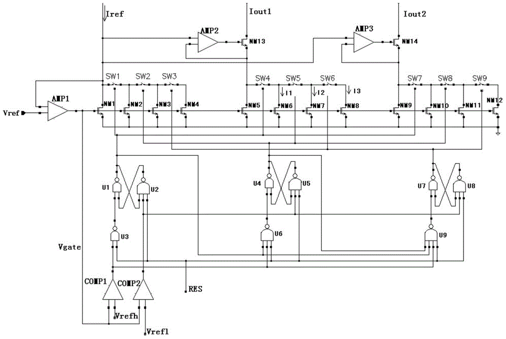
[0069] like Figure 4 As shown, a current mirror with high precision and wide current range, the current mirror with switchable current gears includes a reference current input part I1, a current gear judgment and control logic I3, and a mirrored current output part I2.

[0070] like Figure 4 As shown, the reference current input part I1 includes a current mirror transistor and an operational amplifier AMP1, wherein the current mirror transistor includes a basic transistor NM0 and a spare transistor NM1, a spare transistor NM2, a spare transistor NM3, a basic transistor NM0 and a spare transistor NM1, a spare transistor NM2, The drains of the standby transistor NM3 are connected to the reference current Iref, the sources of the basic transistor NM0 and the standby transistor NM1, the standby transistor NM2, and the standby transistor NM3 are connected to each other, and the gates of the standby transistor NM1, the standby transistor NM2, and the standby transistor NM3 are con...

Embodiment 2

[0075] like Figure 5 As shown, a high-precision wide current range current mirror includes a reference current input part I1, a current gear judgment and control logic I8, and several mirror current output parts I2. Preferably, there are multiple mirror current output parts I2. In this embodiment, Two examples are used for illustration, namely, the mirror current output part I2 and the mirror current output part I20 .

[0076] like Figure 5 As shown, the reference current input part I1 includes a current mirror transistor and an operational amplifier AMP1, wherein the current mirror transistor includes a basic transistor NM1 and a spare transistor NM2, a spare transistor NM3, a spare transistor NM4, a basic transistor NM1 and a spare transistor NM2, a spare transistor NM3, The drains of the standby transistor NM4 are connected to the reference current Iref, the sources of the basic transistor NM1 and the standby transistor NM2, the standby transistor NM3, and the standby tr...


PUM


Abstract

The invention provides a high-precision and wide-current-range current mirror. The high-precision and wide-current-range current mirror comprises a reference current input part, a current gear judgment and control logic and an image current output part. The reference current input part and the image current output part are connected with the current gear judgment and control logic. The high-precision and wide-current-range current mirror has the advantages that the current mirror capable of working in a linear area in a current gear switching mode is adopted, a current mirror circuit is improved, the VDS voltage precision is improved, accordingly, the current mirror image precision is improved, and the current mirror image range is widened.

Description

technical field [0001] The invention relates to a current mirror, in particular to a current mirror with high precision and wide current range. Background technique [0002] In analog circuits, current mirrors are often used to generate circuit bias currents, load currents, and accurate reference currents. Such as figure 1 As shown, the current mirror used often adopts a saturated tube mirror. The source-drain current formula of the MOS tube operating in the saturation region and only considering the first-order effect is shown in formula (1). The adjacent MOS tubes have their µ n 、C ox It is the same as VTH. It is known from formula (1) that if VGS is the same, the drain-source current ID of the two MOS transistors is only proportional to W / L. Such as figure 1 Currents I1 and I2 are shown proportional to Iref. [0003] However, there are secondary effects and channel length modulation effects in MOS transistors. Just as the voltage difference between the gate and dr...

Claims


Application Information

Patent Timeline
IPC IPC(8): G05F3/26
Inventor 李科举秦鹏举
Owner SHENZHEN FM ELECTRONICS GRP CO LTD
Why Eureka
Try Eureka