
Battery sleeve machine

A casing machine and casing technology, applied in the mechanical field, can solve the problems of inserting battery cells into the casing, waste of casing materials, and high labor costs, and achieve the effects of avoiding waste, facilitating maintenance and repairing, and having a high degree of automation.

Active Publication Date: 2015-10-07
平南县富时达自动化设备有限公司
View PDF3 Cites 9 Cited by
  • Summary
  • Abstract
  • Description
  • Claims
  • Application Information

AI Technical Summary

Problems solved by technology

[0003] At present, there are only battery heat-shrinkable film sleeve opening equipment on the market. This type of sleeve opening equipment mostly uses vacuum suction to suck open, because there are differences in the thickness specifications of the heat-shrinkable film of various manufacturers, and the same roll of heat-shrinkable film There may also be uneven thickness, and the vacuum suction needs to be preset, and then maintain a constant suction to open the heat shrinkable film sleeve, which makes it possible that the thicker heat shrinkable film sleeve cannot be vacuumed due to insufficient suction. Opening will cause waste of sleeve material and may affect the subsequent process. This is also the reason why the battery cell cannot be automatically inserted into the sleeve after the sleeve is opened.
[0004] Therefore, the prior art equipment is only automatic to the process of opening the heat-shrinkable film. There is no way to insert the battery core into it while opening the heat-shrinkable film sleeve. This step is often done manually, and the efficiency is low. Slow speed and high labor cost

Method used


Image

  • Battery sleeve machine
  • Battery sleeve machine
  • Battery sleeve machine

Examples


Embodiment Construction

[0032] A kind of embodiment of the present invention is described below in conjunction with accompanying drawing:

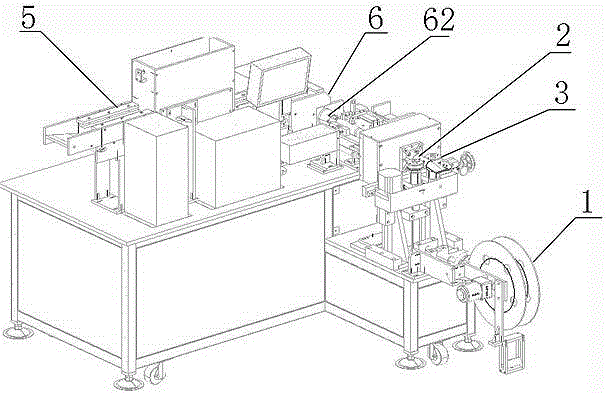
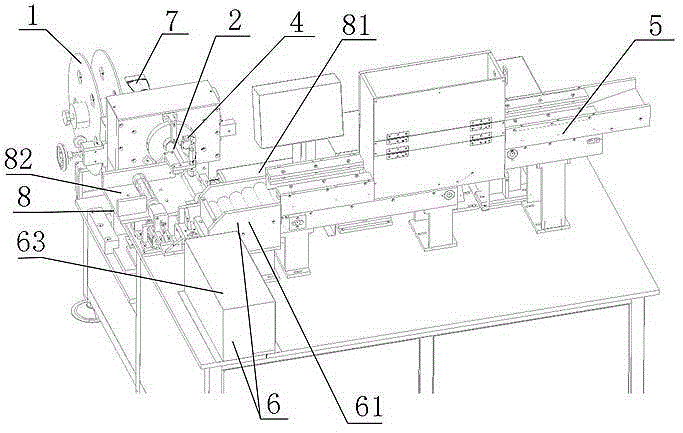
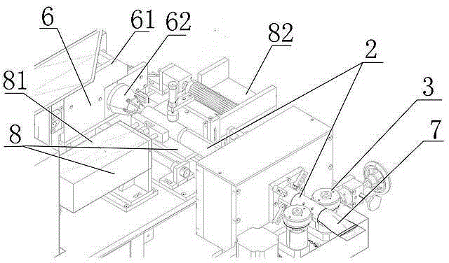
[0033] Such as Figure 1-Figure 3 As shown, the battery casing machine of the present invention includes a casing conveying and cutting mechanism and a battery core conveying mechanism;

[0034] The casing conveying and cutting mechanism includes a casing reel 1, a spreading column 2, a transmission wheel 3, and a cutting device 4;

[0035] The battery core conveying mechanism includes a battery core conveying device 5 and a battery core ejecting device 6; the end of the battery core conveying device 5 is provided with a battery core ejecting device 6;

[0036] A casing coil tape is installed on the casing coil reel 1, and one end of the stretching column 2 is a stretching end 7, and the stretching end 7 is a structure in which the cylinder gradually gathers toward a flat state, and the flat side is located at At the outermost side, the sleeve coil tape extends...


PUM


Abstract

The invention provides a battery sleeve machine. The battery sleeve machine provided by the invention comprises a sleeve conveying and cutting mechanism and a battery cell conveying mechanism, wherein the sleeve conveying and cutting mechanism comprises a sleeve coil disc, an expanding column, a conveying wheel and a cutting device; the battery cell conveying mechanism comprises a battery cell conveying device and a battery cell ejection device; the battery cell ejection device is arranged at the tail end of the battery cell conveying device. According to the battery sleeve machine provided by the invention, the disadvantages of a vacuum suction force expansion sleeve technology in the prior art are overcome; an expanding column structure with a unique design is matched with the conveying wheel so that a battery thermal shrinkage film sleeve can be completely expanded and the waste of materials is avoided; the battery sleeve machine lays the foundation of full automatic proceeding of a battery cell sleeve procedure and has a good application prospect.

Description

technical field [0001] The invention relates to the mechanical field, in particular to a battery casing machine. Background technique [0002] At present, in the battery field, in order to make the appearance of the battery more beautiful and protect the battery from external impacts, the side walls of the battery are covered with a heat-shrinkable film to protect the battery after heat-shrinking. [0003] At present, there are only battery heat-shrinkable film sleeve opening equipment on the market. This type of sleeve opening equipment mostly uses vacuum suction to suck open, because there are differences in the thickness specifications of the heat-shrinkable film of various manufacturers, and the same roll of heat-shrinkable film There may also be uneven thickness, and the vacuum suction needs to be preset, and then maintain a constant suction to open the heat shrinkable film sleeve, which makes it possible that the thicker heat shrinkable film sleeve cannot be vacuumed d...

Claims


Application Information

Patent Timeline
Patent Type & Authority Applications(China)
IPC IPC(8): H01M2/02H01M6/00H01M10/04
CPCH01M6/005H01M10/0404H01M50/10Y02P70/50
Inventor 林科晓何国良林科标林科林
Owner 平南县富时达自动化设备有限公司
Learn More