Check patentability & draft patents in minutes with Patsnap Eureka AI!

Control logic circuit with low fan-in

A technology for controlling logic circuits and logic circuits, applied in electrical components, electrical signal transmission systems, signal transmission systems, etc., can solve the difficulties in designing high-speed comparators, the increase of comparator load capacitance, and the time limit of comparator speed DAC network establishment and other issues to achieve the effect of reducing fan-out, fast speed, and fast work

Inactive Publication Date: 2015-10-07
XIDIAN UNIV
View PDF3 Cites 0 Cited by
  • Summary
  • Abstract
  • Description
  • Claims
  • Application Information

AI Technical Summary

Problems solved by technology

The design of a high-speed SAR ADC is mainly limited by the speed of the comparator and the settling time of the DAC network
With the improvement of the accuracy of SAR ADC, the load capacitance of the comparator will increase a lot when using the traditional control logic circuit, which makes the design of high-speed comparator more difficult

Method used


Image

  • Control logic circuit with low fan-in
  • Control logic circuit with low fan-in
  • Control logic circuit with low fan-in

Examples


Embodiment Construction

[0033] The control logic of the present invention resides in the analog-to-digital converter.

[0034] The present invention will be specifically introduced below in conjunction with the accompanying drawings and specific embodiments.

[0035] First, the structure of the control logic circuit of the present invention is introduced.

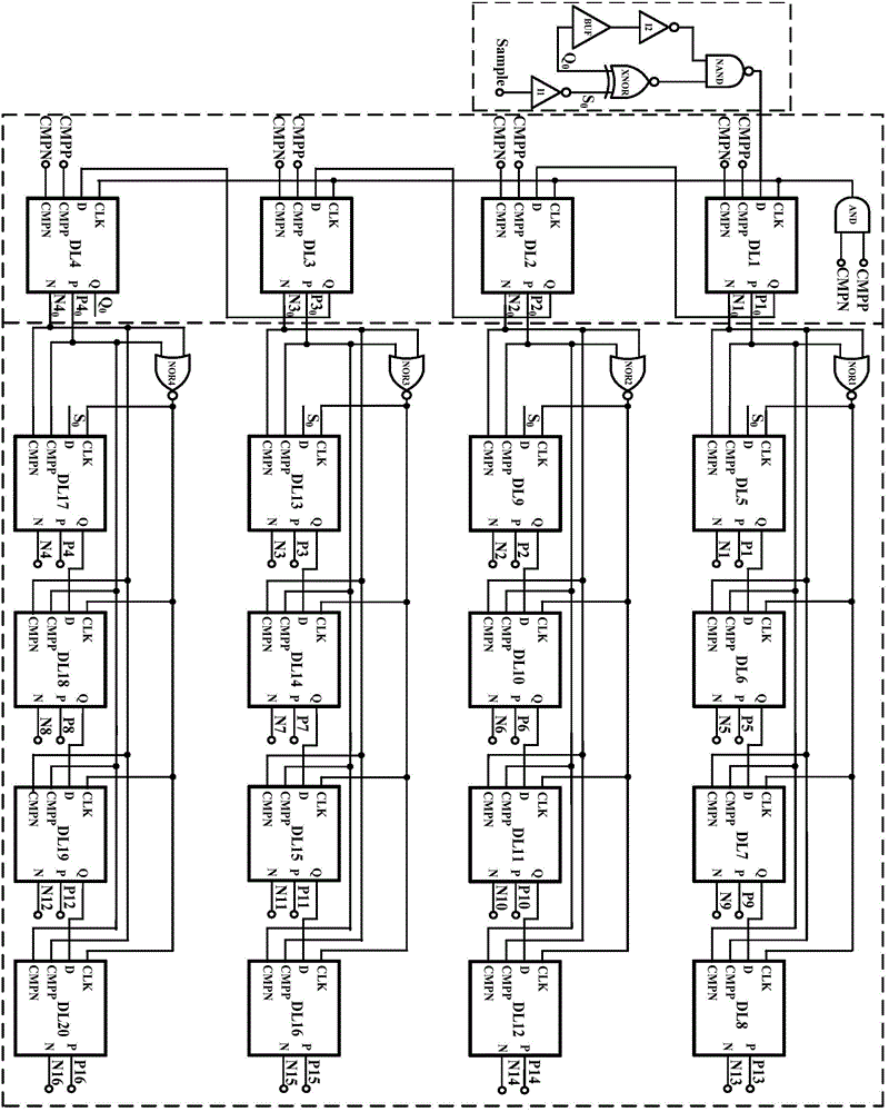
[0036] refer to figure 1 , the control logic circuit with low fan-in of the present invention, which includes: a main control logic trigger circuit, a main control logic circuit and a sub-control logic circuit, wherein the main control logic trigger circuit is used to generate a trigger signal to make the main control logic circuit work ; The main control logic circuit is used to generate the input of the sub-control logic circuit, which includes 1 AND gate and 4 identical dynamic logic units, and the 4 dynamic logic units are used to divide the 16 comparison results of the comparator into 4 groups sequentially Perform latching; the sub-control ...


PUM


Abstract

The invention discloses a control logic circuit with low fan-in. The control logic circuit is characterized in that the control logic circuit comprises a main control logic trigger circuit, a main control logic circuit and a sub control logic circuit; the main control logic trigger circuit is used for generating a triggering signal driving the main control logic circuit to work; the main control logic circuit is used for generating input of the sub control logic circuit and comprises an and gate and four same dynamic logic units; the dynamic logic units are used for dividing 16 comparison results of a comparator into four groups and latching the four groups in order; each sub control logic circuit comprises four NOR gates and 16 same dynamic logic units, and the dynamic logic units are used for latching and outputting 16 latching results of the main control logic circuit. The beneficial effects of the control logic circuit with low fan-in are that the control logic circuit has low fan-in in the premise of meeting low-latching time, fan-out of a comparator is lowered, and thus the comparator can work in a high speed.

Description

technical field [0001] The invention relates to a control logic circuit, in particular to a control logic circuit with low fan-in, and belongs to the field of analog integrated circuits. Background technique [0002] SAR ADC (Successive Approximation Analog-to-Digital Converter) has become a research hotspot in the industry and academia in recent years due to its advantages such as simple structure, low power consumption, easy integration, and small area. The design of a high-speed SAR ADC is mainly limited by the speed of the comparator and the settling time of the DAC network. With the improvement of the precision of SAR ADC, the load capacitance of the comparator will increase a lot when the traditional control logic circuit is adopted, which makes the design of the high-speed comparator more difficult. If the number of dynamic logic units in the control logic part can be reduced to reduce the load capacitance of the comparator, the speed of the comparator will be greatl...

Claims


Application Information

Patent Timeline
Patent Type & Authority Applications(China)
IPC IPC(8): H03M1/38
Inventor 王玉涛姚娇娇朱樟明梁宇华杨银堂
Owner XIDIAN UNIV
Features
  • R&D
  • Intellectual Property
  • Life Sciences
  • Materials
  • Tech Scout
  • Unparalleled Data Quality
  • Higher Quality Content
  • 60% Fewer Hallucinations
Learn More