
Camera module detection equipment

A technology of camera module and detection equipment, applied in image communication, television, electrical components and other directions, can solve the problems of health hazards, high missed detection rate, slow detection speed of detection personnel, etc., and achieve low missed detection rate, high precision, Automate the effect

Active Publication Date: 2015-10-07
东莞市升宏智能科技有限公司
View PDF6 Cites 17 Cited by
  • Summary
  • Abstract
  • Description
  • Claims
  • Application Information

AI Technical Summary

Problems solved by technology

[0006] The present invention provides a camera module detection device in order to solve the problems of slow detection speed, high missed detection rate and easy harm to the health of the detection personnel that exist in the current human eye detection camera module

Method used


Image

  • Camera module detection equipment
  • Camera module detection equipment
  • Camera module detection equipment

Examples


Embodiment Construction

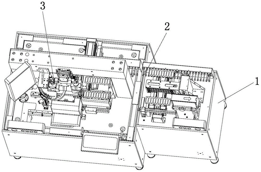
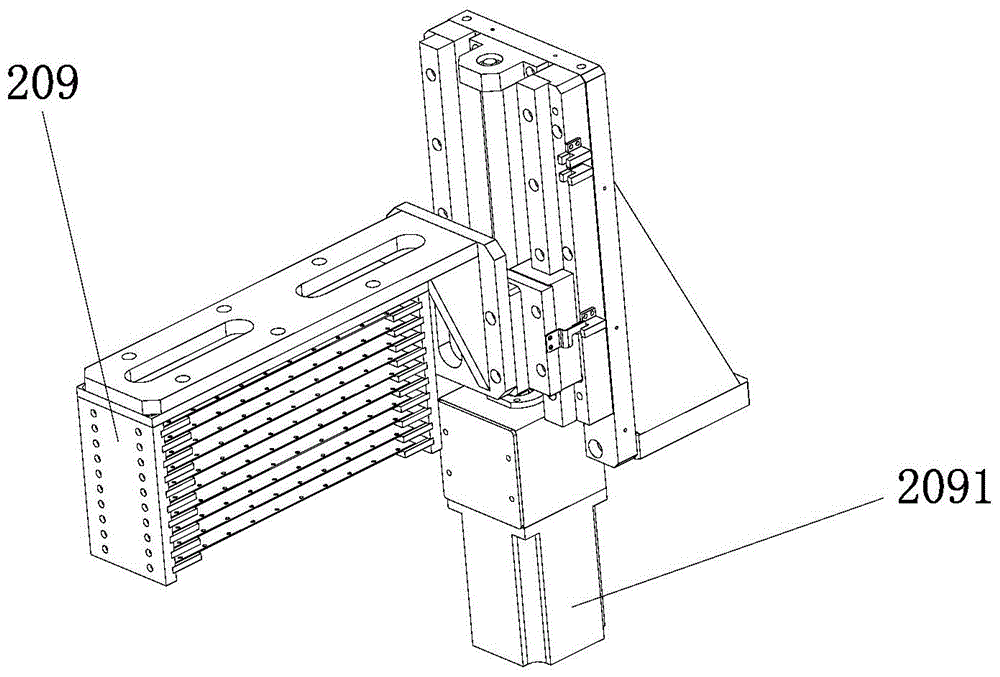
[0028] Attached below figure 1 to attach Image 6 The present invention is described further:

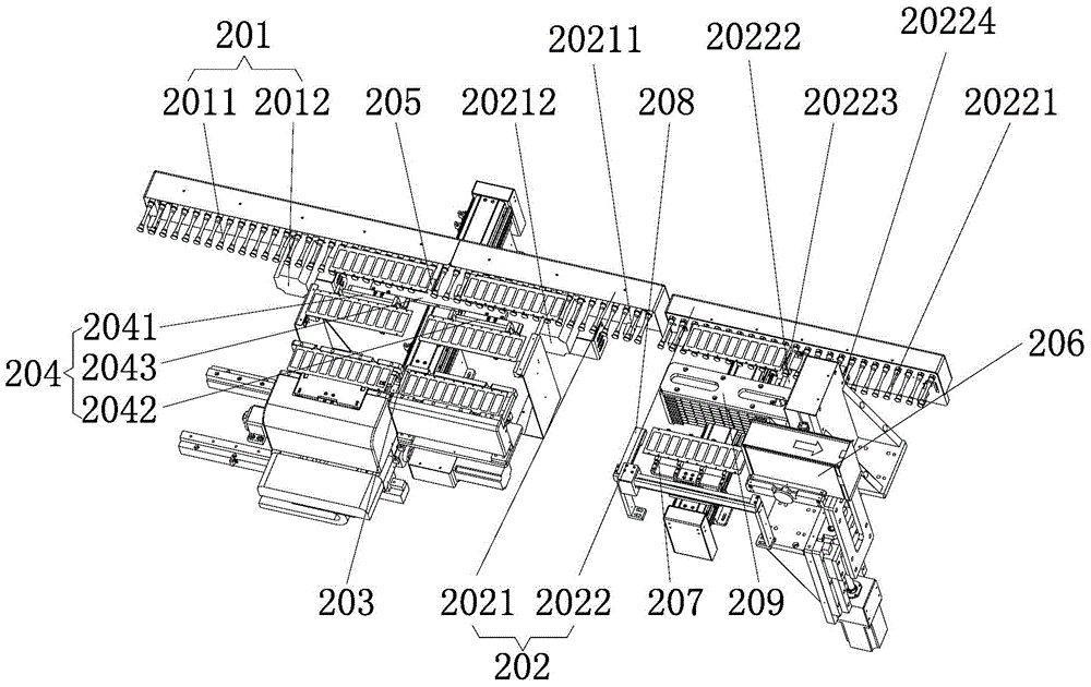
[0029] Such as figure 1 The shown camera module testing equipment includes a frame 1 , a transmission device 2 and an optical system 3 , and the transmission device 2 and the optical system 3 are installed on the frame 1 .

[0030] Such as figure 2 As shown, the conveying device 2 includes an input conveyor belt 201, an output conveyor belt 202, a detection conveyor belt 203 and a lateral conveying mechanism 204, the input conveyor belt 201 and the output conveyor belt 202 are sequentially docked and arranged, and the detection conveyor belt 203 is arranged in parallel with the input conveyor belt 201 and the output conveyor belt 202, In this embodiment, the middle of the detection conveyor belt 203 is located at the butt joint between the input conveyor belt 201 and the output conveyor belt 202 .

[0031] A stopper A205 is arranged between the input conveyor belt 201 and the o...


PUM


Abstract

The invention relates to the technical field of mobile phone camera module detection equipment, and particularly relates to camera module detection equipment, which comprises a rack, a transmission device and an optical system. Transmission of a material plate among an input transmission belt, a detection transmission belt and an output transmission belt is realized via a lateral transport mechanism, and output via the output transmission belt is finally carried out. After a camera module is transported on the detection transmission belt, with the help of a first light source group, a second light source group and a third light source group, a first camera and a second camera of the optical system realize detection on a gold wire on a circuit connection substrate on an image sensor group and detection on dust and scratches of the image sensor respectively, and after detection, output via the output transmission belt is carried out. Full-automatic transport of the material plate is realized, the automatic degree of the camera module detection equipment is improved, the working efficiency is improved, automatic detection of the camera module is realized, the detection efficiency is high, the precision is high, and the detection mission rate is low.

Description

technical field [0001] The invention relates to the technical field of mobile phone camera module testing equipment, in particular to a camera module testing equipment. Background technique [0002] With the advancement of technology, mobile phones are becoming more and more intelligent and have more and more functions. Today's smartphones are equipped with cameras. [0003] The camera function is realized by a camera module, which generally includes a lens group, a focus motor, a filter, an image sensor and a circuit connection substrate. If there is dust or scratches on the image sensor, it will directly affect the imaging effect. The gold wire on the wire connection substrate is an important channel for data transmission, and the gold wire is thin and dense. When there is a disconnection, short circuit or missing solder, it will also affect the transmission of relevant data on the sensor and affect the imaging effect. [0004] After the image sensor and the circuit con...

Claims


Application Information

Patent Timeline
Patent Type & Authority Applications(China)
IPC IPC(8): H04N17/00
Inventor 张舞杰谢长贵
Owner 东莞市升宏智能科技有限公司
Learn More