Adjustable transmission rack for feeding of cutter

An adjustable and cutting machine technology, applied in shearing devices, accessories of shearing machines, metal processing equipment, etc., can solve the problems of increased inconvenience, different steel specifications, and inability to adjust the height of the roller shaft of the conveyor. Improve convenience and solve the effect of loud noise

Inactive Publication Date: 2015-10-14
SHANGHAI SHENGJIAN ENVIRONMENTAL PROTECTION SCI & TECH
View PDF0 Cites 2 Cited by
  • Summary
  • Abstract
  • Description
  • Claims
  • Application Information

AI Technical Summary

Problems solved by technology

[0002] In the mechanical processing industry, it is necessary to cut some long steel materials, and then do further finishing by lathes, milling machines, and grinders. The ordinary transmission frame has the following disadvantages. 1. The transmission frame is a fixed structure, which is not easy to move; 2. .The height of the roller shaft of the transmission frame cannot be adjusted, and the specifications of the steel to be processed are different, resulting in a height difference between the transmission frame and the cutting machine, which further increases the inconvenience during processing; 3. The roller shaft is a bare surface structure, and the steel is placed Scratches are easy to occur on the upper surface of the transfer frame and the noise is particularly loud during operation

Method used


Image

  • Adjustable transmission rack for feeding of cutter
  • Adjustable transmission rack for feeding of cutter

Examples


Embodiment Construction

[0016] Below in conjunction with accompanying drawing and embodiment the present invention is described in further detail:

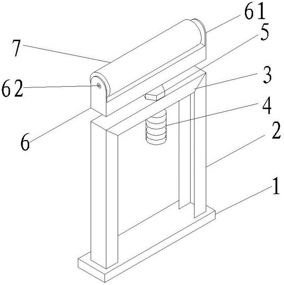
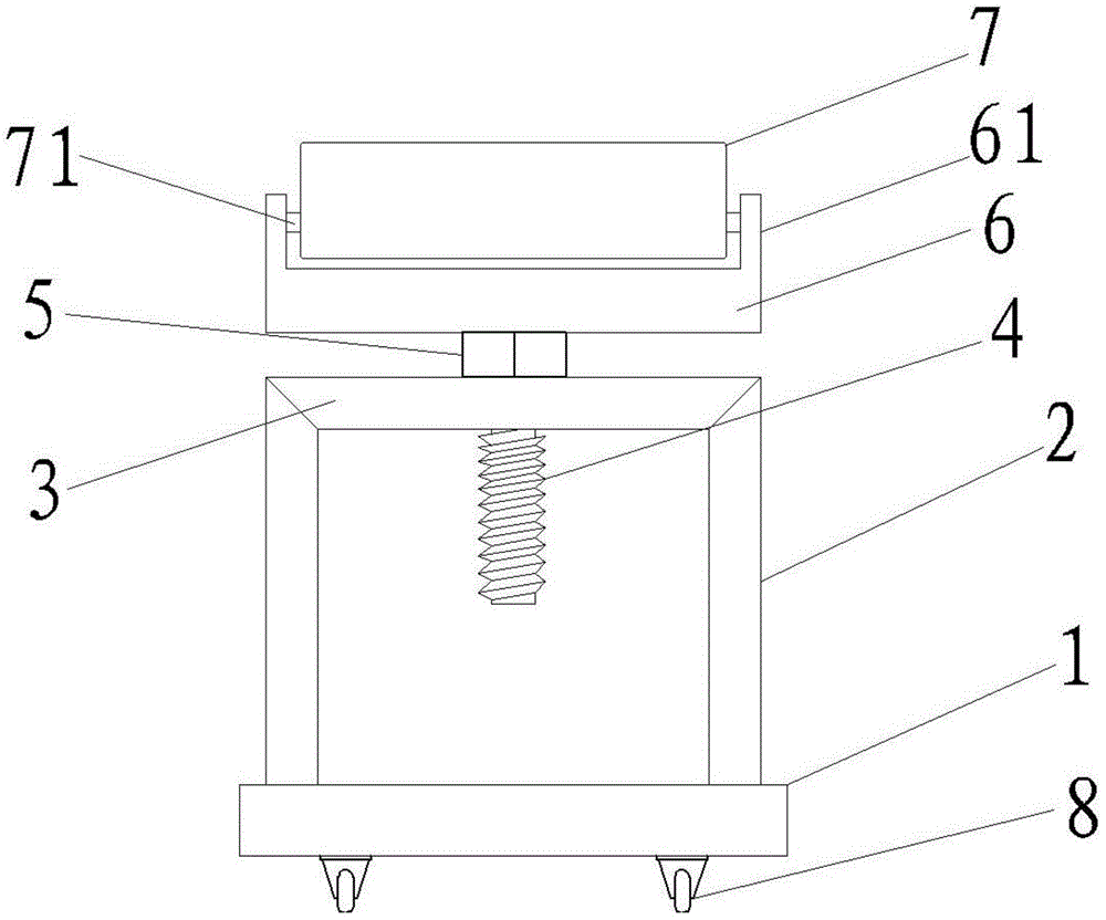
[0017] see Figure 1-2 , an adjustable transfer frame for cutting machine feeding, which has:

[0018] Base 1, casters 8 are fixed on both sides of the bottom surface of the base 1, and the base 1 is convenient to move through the casters 8;

[0019] The supporting body, the supporting body includes vertical beams 2 arranged perpendicular to the base, the vertical beams 2 are arranged on both sides of the side of the base 1, and can be fixed with the base 1 by welding, and a cross beam 3 is connected between the tops of the vertical beams 2, and the cross beams The middle part of 3 has the through hole that runs through beam 3.

[0020] Lifting assembly, the lifting assembly includes a frame body 6, lugs 61 are respectively formed on both sides of the frame body 6, a roller shaft 7 is fixed between the lugs 61, a screw rod 4 is vertically fixed on the ...


PUM


Abstract

The invention discloses an adjustable transmission rack for feeding of cutter, which comprises a pedestal, a support body and an elevating assembly, wherein the elevating assembly comprises a rack body, lugs are formed on two sides of the rack body, a roll shaft is fixed between the lugs, a screw is vertically fixed on the bottom surface of the rack body, the screw is arranged through a through hole on a crossbeam of the support body to arrange the rack body on the top of the crossbeam, a nut which can adjust vertical elevating of the screw is fixed on the screw tightly close to the upper part of the crossbeam, the elevating of the roll shaft fixed on the rack body is realized through adjustment of the height of the nut, so as to change the height of steel arranged on the roll shaft and solve the problem of size difference of the steel and height difference between the transmission rack and the cutter.

Description

technical field [0001] The invention relates to the technical field of mechanical processing equipment, in particular to an adjustable conveying frame used for cutting machine feeding. Background technique [0002] In the mechanical processing industry, it is necessary to cut some long steel materials, and then do further finishing by lathes, milling machines, and grinders. The ordinary transmission frame has the following disadvantages. 1. The transmission frame is a fixed structure, which is not easy to move; 2. .The height of the roller shaft of the transmission frame cannot be adjusted, and the specifications of the steel to be processed are different, resulting in a height difference between the transmission frame and the cutting machine, which further increases the inconvenience during processing; 3. The roller shaft is a bare surface structure, and the steel is placed Scratches are easy to occur on the upper surface of the transfer frame and the noise during operation...

Claims


Application Information

Patent Timeline
Patent Type & Authority Applications(China)
IPC IPC(8): B23D33/02
Inventor 谢勍
Owner SHANGHAI SHENGJIAN ENVIRONMENTAL PROTECTION SCI & TECH
Why Eureka
Try Eureka