
Vaneless gas turbine power generation device

A gas turbine and power generation device technology, applied in the direction of gas turbine devices, machines/engines, mechanical equipment, etc., can solve the problems of difficult manufacturing, complex blade structure, high design requirements, etc., to solve manufacturing and maintenance, simplify system structure, and device structure simple effect

Inactive Publication Date: 2015-10-14
BEIJING INSTITUTE OF TECHNOLOGYGY
View PDF5 Cites 8 Cited by
  • Summary
  • Abstract
  • Description
  • Claims
  • Application Information

AI Technical Summary

Problems solved by technology

The miniaturized blade has a complex structure, high design requirements, difficult manufacturing, and difficult to guarantee reliability under complex working conditions, which brings difficulties to the miniaturization of the whole machine and restricts the development of micro gas turbine power generation devices

Method used


Image

  • Vaneless gas turbine power generation device
  • Vaneless gas turbine power generation device
  • Vaneless gas turbine power generation device

Examples


Embodiment Construction

[0018] The present invention will be further described in detail below in conjunction with the accompanying drawings and embodiments.

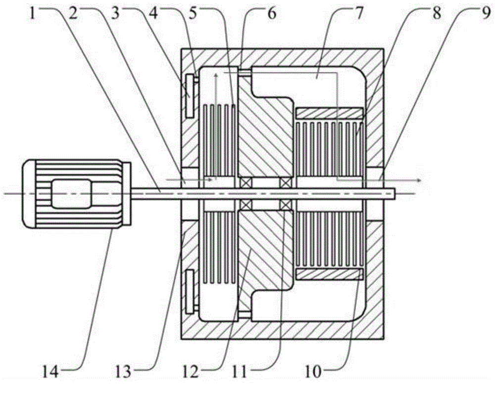
[0019] This embodiment provides a bladeless gas turbine power generation device, which includes: a gas turbine body and a motor 14 .

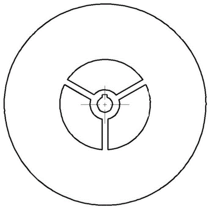
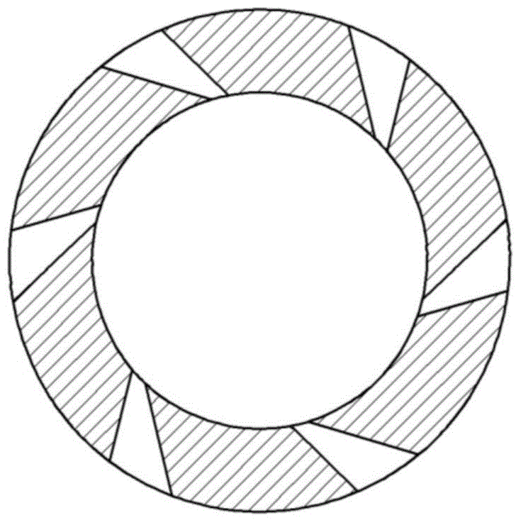
[0020] Wherein the gas turbine body comprises: housing 13, compressor disc group 5, turbine disc group 8 and gas guider 10; housing 13 two ends are respectively provided with air inlet 2 and air outlet 9, on the air inlet 2 side The housing 13 is provided with a fuel chamber 3 and a fuel nozzle 4; the interior of the housing 13 is divided into two cavities by a middle partition 12, wherein the cavity on the side of the air inlet 2 is a mixture chamber, and the side of the air outlet 9 The cavity is the combustion chamber 7; the combustion chamber 7 communicates with the gas mixture chamber through the flame holder 6 arranged on the intermediate partition 12; image 3 As shown, the gas guide 10 is arranged in t...


PUM


Abstract

The invention relates to the energy utilization technical field, and relates to a power generation device. Provided is a vaneless gas turbine power generation device which comprises a gas turbine body and a motor; the technical scheme comprises that a gas turbine part adopts a vaneless gas compressor and a gas turbine structure, a group of coaxially-parallel thin disks separated with equal small spacing are used for replacing a vane structure of a conventional gas turbine. A rotor shaft of the power generation device rotates at high speed along with a central shaft of the gas turbine to generate power and output electric power to the outside. Through matching the gas turbine with the motor, the starting problem of the gas turbine is solved; at the same time, when the gas turbine reaches a stable work state, a rotor of the power generation device is driven to rotate, the electric power output is achieved, and a complete power generation system is formed.

Description

technical field [0001] The invention relates to the technical field of energy utilization, in particular to a power generating device. Background technique [0002] With the need for environmental protection and the development trend of electricity market liberalization, the traditional centralized power supply mode based on large, inefficient, heavily polluting power plants far away from consumers needs to be changed, and the distributed power supply mode has emerged. The distributed power supply system can make up for the lack of security and stability of the large power grid and realize emergency power supply; the distributed power supply system can also be used in many occasions where the power supply is not centralized, and users can generate electricity nearby to meet the needs of decentralized power consumption. Small, clean, reliable and inexpensive power generation units form the basis for decentralized power supply. Due to its high energy utilization rate, high po...

Claims


Application Information

Patent Timeline
Patent Type & Authority Applications(China)
IPC IPC(8): F02C6/00F02C3/04F02C3/14
Inventor 吴维胡晨晖苑士华胡纪滨
Owner BEIJING INSTITUTE OF TECHNOLOGYGY
Learn More