Engine fuel injection quantity control device

A fuel injection quantity and control device technology, applied in fuel injection control, engine control, machine/engine, etc., can solve the problem that it is difficult to maintain the air intake of the product intact

Active Publication Date: 2017-08-15
AISAN IND CO LTD
View PDF4 Cites 0 Cited by
  • Summary
  • Abstract
  • Description
  • Claims
  • Application Information

AI Technical Summary

Problems solved by technology

If such deposits adhere to the air intake system, it will become an obstacle to air flow, so it is difficult to maintain the original air intake of the product intact

Method used


Image

  • Engine fuel injection quantity control device
  • Engine fuel injection quantity control device
  • Engine fuel injection quantity control device

Examples


no. 1 Embodiment approach >

[0042] Hereinafter, the first embodiment embodying the fuel injection amount control device of the engine of the present invention will be described in detail with reference to the drawings.

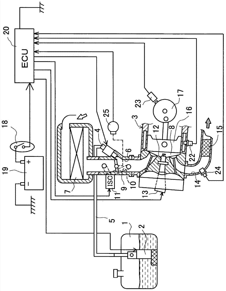
[0043] figure 1 A schematic configuration diagram is used to show the engine system of this embodiment. The engine system mounted on the two-wheeled vehicle includes a fuel tank 1 for storing fuel. The fuel pump 2 built in the fuel tank 1 ejects the fuel stored in the tank 1. The reciprocating single-cylinder engine 3 is provided with an injector 4 corresponding to an example of the fuel injection means of the present invention. The fuel ejected from the fuel pump 2 is supplied to the injector 4 through the fuel passage 5. When the injector 4 opens the valve, the supplied fuel is injected into the intake passage 6. Air is sucked into the intake passage 6 from the outside via the air cleaner 7. The air drawn into the intake passage 6 and the fuel injected from the injector 4 form a comb...

no. 2 Embodiment approach >

[0076] Next, a second embodiment embodying the fuel injection amount control device for an engine of the present invention will be described in detail with reference to the drawings.

[0077] In addition, in the following description, the same reference numerals are given to the same components as those of the first embodiment, and the description is omitted, and the description will be centered on the differences. In the present embodiment, a part of the structure is different from the first embodiment in the content of the intake air amount calculation program for estimating and calculating the intake air amount Ga.

[0078] Generally speaking, in the intake passage 6 and the bypass passage 10, deposits sometimes adhere to the inner wall to narrow the flow path area, and the deposits sometimes adhere to the throttle valve 9 and the ISC valve 11. In addition, the amount of deposits will increase over time. If such deposits adhere to the intake system, it will become an obstacle t...

no. 3 Embodiment approach >

[0097] Next, a third embodiment embodying the fuel injection amount control device for an engine of the present invention will be described in detail with reference to the drawings.

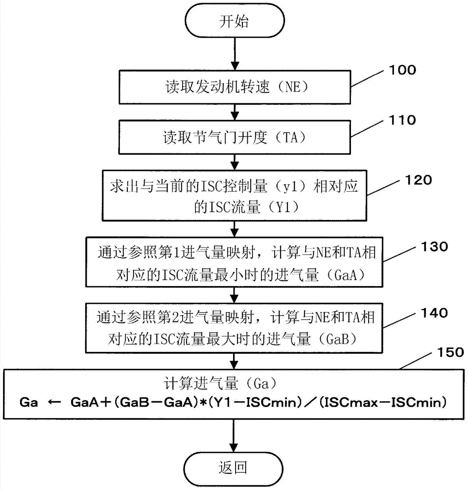
[0098] In this embodiment, a part of the structure is different from the second embodiment in the content of the intake air amount calculation program for estimating and calculating the intake air amount Ga. Figure 14 The intake air amount calculation routine of this embodiment is shown by a flowchart. in Figure 14 In the flowchart, the processing content other than steps 125 and 126 is the same as Picture 11 The processing content of the flowchart is the same.

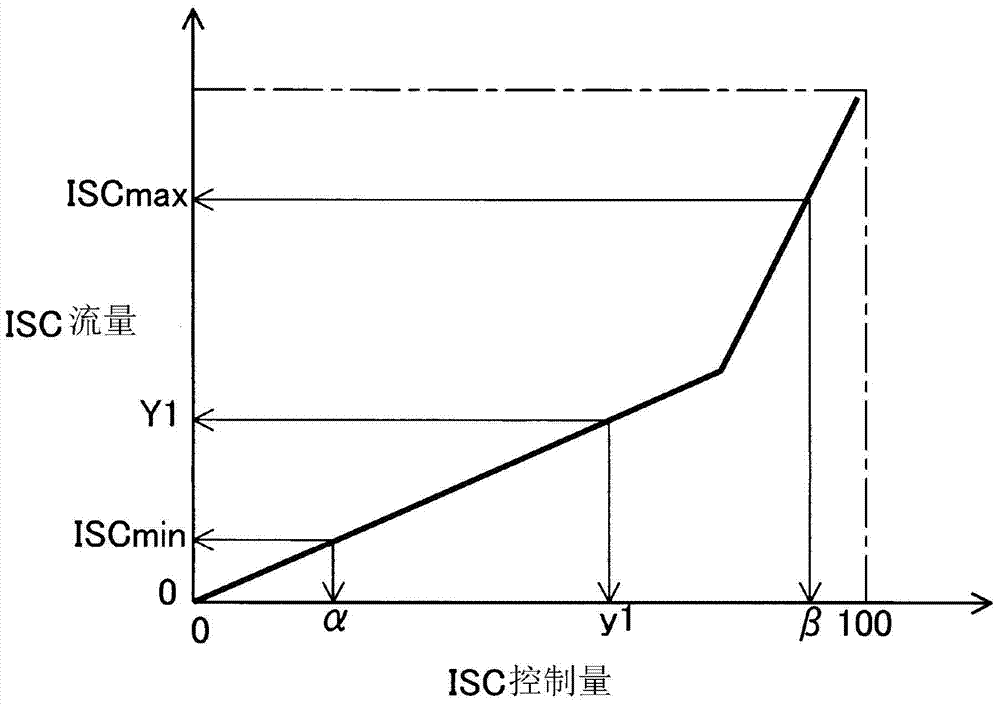
[0099] When the process is switched to this routine, after the processes of steps 100, 110, 111, 120, and 121 are executed, in step 125, the ECU 20 calculates the ISC learning correction value X2 from the ISC flow learning value X1. Here, ECU20 refers to Figure 15 The illustrated correction map obtains the ISC learning correction value X2...


PUM


Abstract

The present invention provides a fuel injection amount control device for an engine, which uses an α-N method, estimates an intake air amount to be introduced into a combustion chamber with higher accuracy, and appropriately controls fuel injection based on the estimated intake air amount. quantity. An electronic control unit ECU (20) estimates an intake air amount Ga based on a throttle opening TA and an engine speed NE, and controls an injector (4) based on a fuel injection amount TAU ​​calculated from the Ga. The ECU (20) performs the following operations when the engine is running: refer to the ISC flow rate characteristic data to obtain the current ISC flow rate relative to the current ISC control amount, and refer to the first intake air amount map to obtain the relationship between the ISC flow rate and TA and The first intake air amount GaA corresponding to NE, and the second intake air amount GaB corresponding to TA and NE when the ISC flow rate reaches the maximum value are obtained by referring to the second intake air amount map, based on the current ISC flow rate and the maximum ISC flow rate The relationship between the value and the minimum value is interpolated between GaA and GaB to estimate the current Ga.

Description

Technical field [0001] The present invention relates to a fuel injection amount control device for controlling the fuel injection amount supplied to an engine. In detail, it relates to a configuration that does not use an intake air amount detection component, but estimates the amount of intake air drawn into the engine based on the detected throttle opening and engine speed, and controls fuel injection based on the estimated intake air amount. The amount of fuel injection quantity control device for the engine. Background technique [0002] In the past, in this technology, the basic fuel injection amount is usually calculated by using the intake air amount drawn into the engine and the engine speed as parameters, and various correction items are used to correct the basic fuel injection amount to calculate the final fuel injection amount. . Here, in order to obtain the intake air amount, a so-called α-N method is known in which the intake air amount detecting means such as an a...

Claims


Application Information

Patent Timeline
Patent Type & Authority Patents(China)
IPC IPC(8): F02D41/08F02D41/02
Inventor 西尾俊雄近藤清二
Owner AISAN IND CO LTD
Why Eureka
Try Eureka