Work method of navigation system capable of preventing pileup

A working method and technology of a navigation system, applied in the field of navigation, can solve the problems of short distance between front and rear vehicles, easy to cause rear-end collision accidents, and inability to distinguish between rear vehicles, so as to avoid serial rear-end collisions, with good guidance and good real-time performance.

Inactive Publication Date: 2015-12-23
谢保全
View PDF8 Cites 3 Cited by
  • Summary
  • Abstract
  • Description
  • Claims
  • Application Information

AI Technical Summary

Problems solved by technology

[0002] Existing vehicles often have a short distance between the front and rear vehicles during driving, which can easily cause rear-end collision accidents; in addition, when the front vehicle brakes lightly or abruptly during driving, it is often impossible to distinguish the rear vehicles, and the rear vehicles only It can judge the state of the vehicle in front and control its own speed through the change of sight distance, but when the speed is fast, this judgment is often not timely, which will lead to rear-end collision

Method used


Image

  • Work method of navigation system capable of preventing pileup
  • Work method of navigation system capable of preventing pileup
  • Work method of navigation system capable of preventing pileup

Examples


Embodiment 1

[0043] Such as Figure 10 As shown, the present invention provides a working method of a navigation system. The navigation system includes: a navigation device and an imaging device; the navigation device includes: a gyroscope for obtaining the driving direction of the vehicle, and a A GPS module, a data memory for storing map data and street view data, and a processor module and a display module.

[0044] The working method includes: when the processor module finds that the brake light of the vehicle in front of the lane of the vehicle is on through the camera device, the processor module sends a brake light control signal to the vehicle controller, and the vehicle controller controls the brake light of the vehicle. The brake lights are on to remind the vehicles behind the vehicle to take effective measures in time, pay attention to maintaining the distance between vehicles, avoid rear-end collisions of the vehicles behind, and ensure driving safety.

[0045] When the vehicl...

Embodiment 2

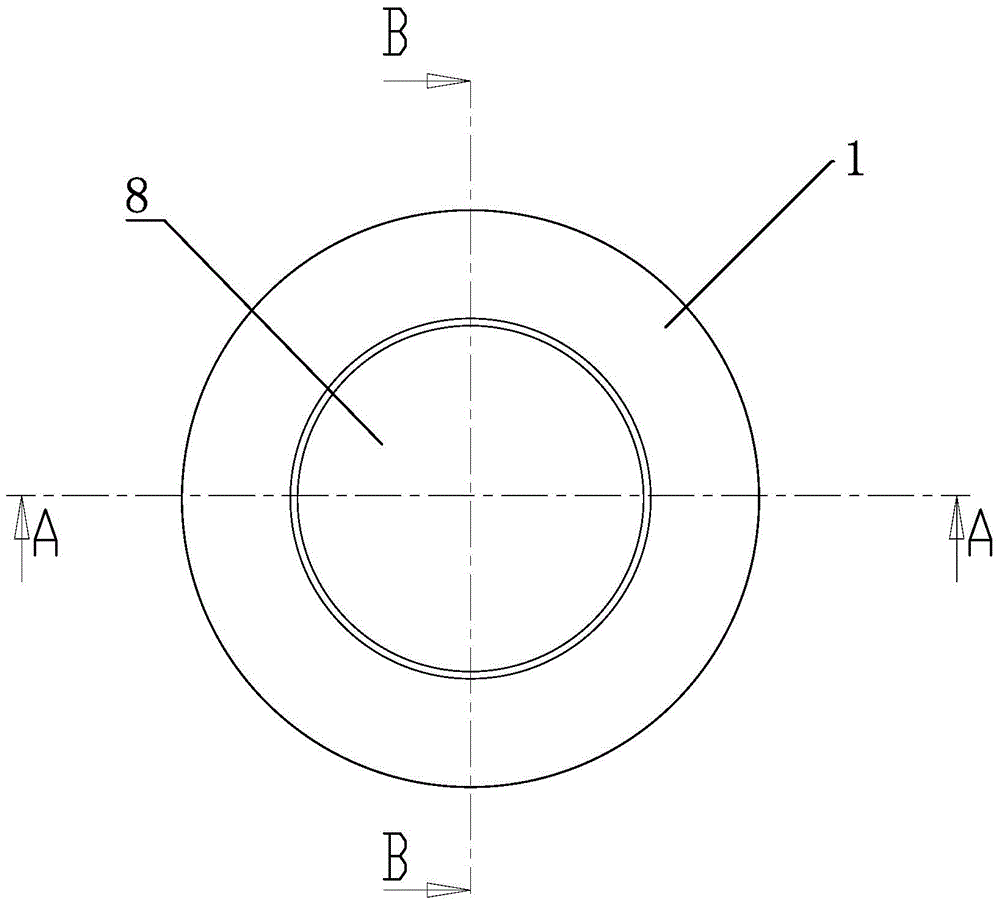
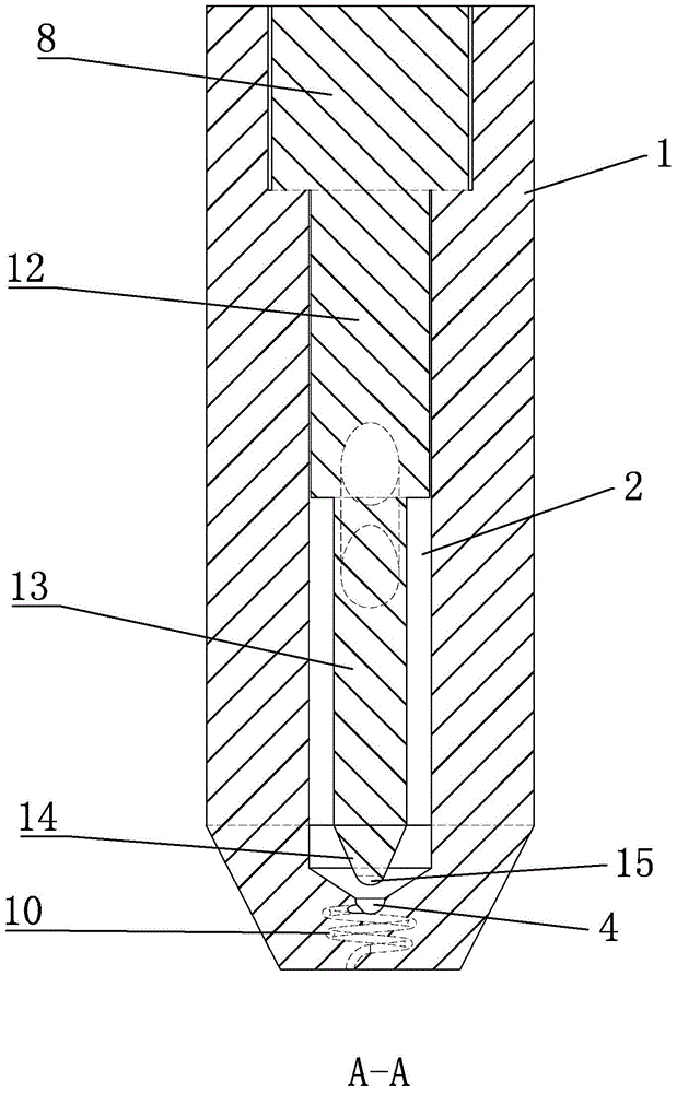
[0057] Such as Figure 1-7 As shown, the anti-carbon deposit fuel injector for vehicles of the present invention includes: valve body 1, plunger chamber 2, tapered chamber 3, valve seat 4, liquid outlet 5, liquid inlet hole 6, control groove 7, control Device 8, liquid injection port 9, drainage channel 10, plunger 11, upper plunger 12, lower plunger 13, cone 14, valve needle 15, lower edge 16.

[0058] The top of the cylindrical valve body 1 is provided with a cylindrical control groove 7, and the lower end of the control groove 7 is provided with a cylindrical plunger chamber 2, the plunger chamber 2 communicates with the control groove 7, and the bottom end of the plunger chamber 2 There is a tapered chamber 3 with the tip pointing down, and the bottom end of the tapered chamber 3 is provided with a valve seat 4 with a hemispherical inner wall. The control groove 7, the plunger chamber 2, the tapered chamber 3, and the valve seat 4 are respectively Set in the valve body 1 ...

Embodiment 3

[0072] Such as Figure 7 As shown, the fuel injector of this embodiment differs from that of Embodiment 2 in that: Figure 8-9 As shown, the liquid inlet hole 6 is located in the middle and upper part of the valve body 1. When the plunger 11 moves to the uppermost position, the liquid inlet hole 6 is connected with the outer surface of the lower plunger 13 and the cylindrical cavity between the plunger cavity 2 so that gasoline is injected into the injector; when the plunger 11 moves to the lowest position, the upper plunger 12 closes the inner end of the liquid inlet hole 6, and the lower end edge 16 of the upper plunger 12 is lower than the liquid inlet hole 6 The lower edge of the inner end is low and the distance G between the two is 0.05-0.25mm (preferably 0.1, 0.15 or 0.2 or 0.24mm).

[0073] The working method of the anti-carbon deposit injector in this embodiment includes:

[0074] (1) The controller 8 keeps the plunger 11 at the lowest position, the outer wall of th...


PUM


Abstract

The invention discloses a work method of a navigation system capable of preventing pileup. The navigation system comprises a navigation device and a plurality of camera devices arranged on the periphery of a vehicle, where the navigation device is installed. The navigation device comprises a processor module, which is connected to the vehicle controller of the vehicle. When the processor module finds out that brake lamp of a vehicle (A), which is in front of the vehicle (B) in the same lane, lights; the processor module sends a brake lamp control signal to the vehicle controller; the vehicle controller controls the brake lamp of the vehicle (B) to light so as to indicate a vehicle (C) behind the vehicle (B) to carry out effective action in time so as to keep a safe distance, thus the vehicle rear-end collision is avoided, so the pileup will not happen, and the traveling safety is guaranteed.

Description

technical field [0001] The invention relates to the field of navigation, in particular to a working method of a navigation system capable of avoiding serial rear-end collisions. Background technique [0002] Existing vehicles often have a short distance between the front and rear vehicles during driving, which can easily cause rear-end collision accidents; in addition, when the front vehicle brakes lightly or abruptly during driving, it is often impossible to distinguish the rear vehicles, and the rear vehicles only It can judge the state of the vehicle in front and control its own speed through the change of sight distance, but when the speed is fast, this judgment is often not timely, which will lead to rear-end collision. After a rear-end collision, a series of rear-end collisions will occur immediately. [0003] How to avoid serial rear-end collisions is a technical problem to be solved in this area. Contents of the invention [0004] The purpose of the present inven...

Claims


Application Information

Patent Timeline
Patent Type & Authority Applications(China)
IPC IPC(8): G01C21/26G01C21/30G01C21/36B60Q1/44F02M59/10F02M61/10
CPCB60Q1/44F02M59/10F02M61/10G01C21/26G01C21/30G01C21/3602
Inventor 不公告发明人
Owner 谢保全
Why Eureka
Try Eureka