
A pneumatic multi-disc friction clutch with piston cylinder rotation

A technology of friction clutches and piston cylinders, which is applied in the direction of friction clutches, clutches, fluid-driven clutches, etc., and can solve problems such as abnormal operation of friction clutches, increased leakage, high purchase, maintenance and repair costs, and expand the application field and application range, reduce manufacturing and use costs, and improve the effect of intelligence

Active Publication Date: 2017-12-01
南京奥德传动科技有限公司
View PDF9 Cites 0 Cited by
  • Summary
  • Abstract
  • Description
  • Claims
  • Application Information

AI Technical Summary

Problems solved by technology

Rotary sealing rings are susceptible to insufficient oil level or limited splash lubricating oil, as well as heat and impurities in the lubricating oil, resulting in poor lubrication and heat dissipation, and the intrusion of impurities, resulting in increased wear and leakage of the sealing part, resulting in insufficient piston air pressure The friction pair of the clutch will slip excessively and the friction and temperature rise will increase, which will further lead to abnormal operation of the friction clutch and shorten the service life
For some machinery, especially special-purpose vehicles, it cannot meet the needs in terms of application occasions, performance, convenience and economy of repair and maintenance.
[0005] Due to the influence of many factors above, it is difficult to select the existing clutch, and the cost of purchase, maintenance and repair is high, and it cannot be used in occasions with rain, dust, narrow space and poor ventilation, such as the power transmission of some special vehicles. The degree of automation of some mechanical equipment such as special-purpose vehicles has become a problem to be solved urgently by those skilled in the art

Method used


Image

  • A pneumatic multi-disc friction clutch with piston cylinder rotation
  • A pneumatic multi-disc friction clutch with piston cylinder rotation

Examples


Embodiment Construction

[0030] The present invention will be further described below with reference to the accompanying drawings and in combination with preferred embodiments.

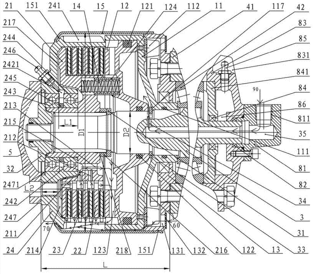
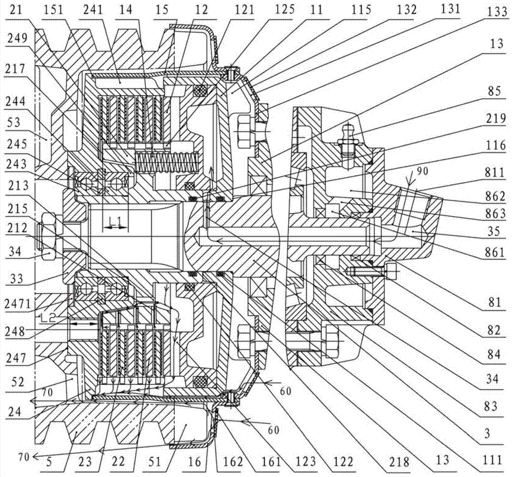
[0031] The invention discloses a pneumatic multi-disc friction clutch of a piston-cylinder rotary type, which is connected between a first transmission device and a second transmission device. shaft, wherein the control air pressure interface device is connected to the first end of the connecting shaft, the second transmission device is arranged on the second end of the connecting shaft, and the connecting shaft is from the first end to the The direction of the second end runs through the first transmission device, the front structure and the rear structure in sequence, the front structure includes a guide seat, a piston cylinder, a piston and a return spring, and the rear structure includes an inner friction plate seat, a plurality of inner friction plates, a plurality of outer friction plates and an outer friction plate con...


PUM


Abstract

The invention discloses a piston cylinder rotation type air pressure multi-disc friction clutch connected between a first transmission device and a second transmission device. The air pressure multi-disc friction clutch comprises a control air pressure connector device, a first transmission device, a front section structure, a rear section structure and a second transmission device which are sequentially connected on a connecting shaft. The front section structure comprises a flow guiding base, a piston cylinder, a piston and a reset spring. The rear section structure comprises an inner friction plate base, a plurality of inner friction plates, a plurality of outer friction plates and an outer friction plate connecting sleeve. The control air pressure connector device comprises a control air pressure connector. The flow guiding base is installed on the first transmission device. The flow guiding base, the piston cylinder, the piston, the reset spring, the inner friction plate base and the outer friction plate connecting sleeve are sequentially connected in a matched mode. The multiple inner friction plates and the multiple outer friction plates are arranged at intervals one by one. The second transmission device is fixedly connected to the outer friction plate connecting sleeve. The air pressure multi-disc friction clutch is compact in structure, good in protection and heat dissipation performance and convenient to maintain.

Description

technical field [0001] The invention relates to an air pressure friction clutch, in particular to a piston-cylinder rotary air pressure multi-plate friction clutch. Background technique [0002] Pneumatic clutches have the advantages of stable combination, large transmission torque, high-frequency clutch and fast action, no need to adjust the gap, and can adapt to automatic control, especially the piston-cylinder rotary pneumatic multi-plate friction clutch and the piston-cylinder fixed pneumatic multi-plate friction clutch. Compared with the clutch, it also has a simple structure, does not need a larger pressure plate and a thrust bearing of the piston cylinder, and can adapt to a higher rotating speed, and is widely used in some medium and large mechanical equipment. [0003] However, in order to ensure generalization and serialization, the existing piston-cylinder rotary air pressure multi-plate clutch adopts an integral bushing structure to facilitate loading and unloadi...

Claims


Application Information

Patent Timeline
Patent Type & Authority Patents(China)
IPC IPC(8): F16D25/0638F16D25/12F16D13/72
Inventor 柯晓贤
Owner 南京奥德传动科技有限公司
Learn More