Arrangement method of bearing hole system of rotary shaft system conforming to deflection curve

A technology of deflection curves and layout methods, which is applied to the transmission of synchronous propulsion components, transmission parts, ship construction, etc., and can solve the problems of partial wear of bearings, uneven stress or pressure at the contact point between bearing holes and shafts, etc.

Active Publication Date: 2015-10-14
HUAZHONG UNIV OF SCI & TECH
View PDF4 Cites 4 Cited by
  • Summary
  • Abstract
  • Description
  • Claims
  • Application Information

AI Technical Summary

Problems solved by technology

Due to the existence of deflection, there will be a relative angle between the central axis of the bearing and the matching shaft. When the shaft rotates, the contact between the bearing hole and the shaft will be uneven, resulting in uneven stress or pressure at the contact between the bearing hole and the shaft, making the bearing The wear amount at different positions along the axial direction is not the same, resulting in eccentric wear of the bearing
The existing propulsion shafting design and technology of reasonable alignment cannot solve the problem of partial wear of bearings, especially the problem of partial wear of the rear bearing of the stern shaft

Method used


Image

  • Arrangement method of bearing hole system of rotary shaft system conforming to deflection curve
  • Arrangement method of bearing hole system of rotary shaft system conforming to deflection curve
  • Arrangement method of bearing hole system of rotary shaft system conforming to deflection curve

Examples


Embodiment Construction

[0036] In order to make the object, technical solution and advantages of the present invention clearer, the present invention will be further described in detail below in conjunction with the accompanying drawings. The description herein is only used to explain the present invention when referring to specific examples, and does not limit the present invention. In addition, the technical features involved in the various embodiments of the present invention described below may be combined with each other as long as they do not constitute a conflict with each other.

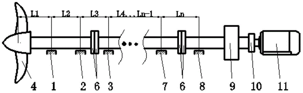
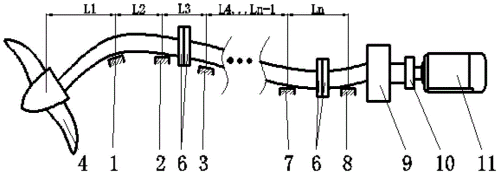
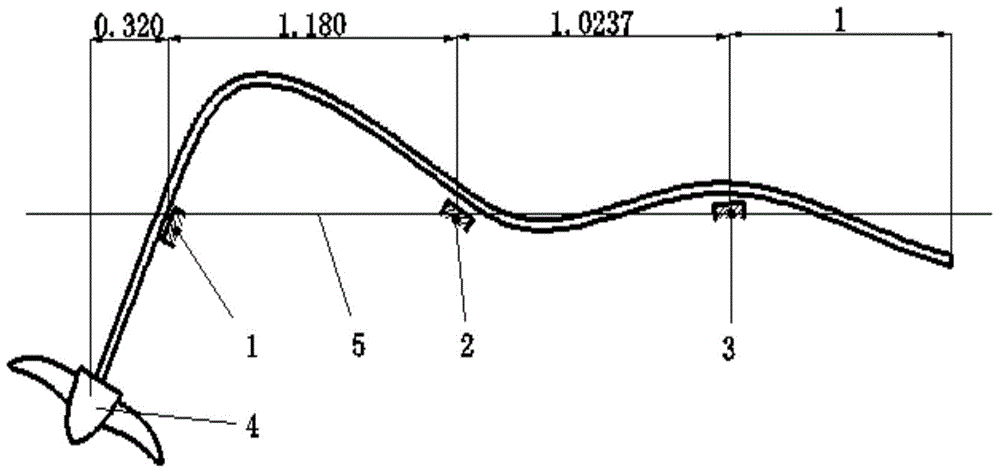
[0037] In this embodiment, three supporting shaft systems are taken as an example to describe the method for arranging bearing holes of the rotating shaft system following the deflection curve. Of course, the method of the present invention is not limited to the above three supporting shaft systems.

[0038] The method for arranging the hole system of the rotating shaft bearing in this embodiment may specifically in...


PUM


Abstract

The invention discloses an arrangement method of a bearing hole system of a rotary shaft system. The arrangement method is characterized in that through the arrangement on positions and deflection angles of axes of bearing holes supporting various bearings of the rotary shaft system, stresses or pressures borne by the single bearing along the same circumferential position and different axial positions are basically consistent, and supporting to the rotary shaft system is realized, and eccentric wear of the bearings of the shaft system is eliminated; and the various bearings are mounted and arranged according to a deflection curve of the shaft system conforming to bearing hole mandrils of the bearings. The method is specific to the rotary shaft system which is provided with three or more bearing holes and has the working conditions that a deflection value and a corner value of the deflection curve of the shaft system at the bearing hole mandril exceed a manufacturing tolerance and a rotary in-service tolerance; and on the steady load condition, the method is applicable to the working condition that the end of the axis of the shaft system bears the load, and also applicable to the working condition that the borne load is in the other axial position in the axis of the shaft system.

Description

technical field [0001] The invention belongs to the technical field of design and manufacture of a rotating shaft system, and in particular relates to a method for arranging a bearing hole system of a rotating shaft system. Background technique [0002] The shaft system is a system composed of shafts, bearings, transmission bodies, seals and positioning components installed on the shafts. Its main function is to support rotating parts, transmit torque and motion. In the shaft system, the position of the bearing directly affects the rotation state of the shaft. The position of the bearing is determined by the arrangement of the bearing hole system. If the bearing hole system is not well arranged, it will cause wear of the bearing, affect the service efficiency of the bearing, and thus affect the life of the shaft system. There may also be serious wear of the bearing, resulting in a significant increase in vibration , and even cause broken shafts. Therefore, the layout meth...

Claims


Application Information

Patent Timeline
Patent Type & Authority Applications(China)
IPC IPC(8): F16H57/021B63H23/34B63B9/00
CPCB63B71/00B63H23/34F16H57/021
Inventor 张新宝董广坤
Owner HUAZHONG UNIV OF SCI & TECH
Why Eureka
Try Eureka