
actuator assembly

A technology of actuators and assemblies, applied in the direction of elements with teeth, transmission control, belt/chain/gear, etc., can solve the problem of impossible to operate two shift rails at the same time, and the shift shaft cannot be rotated, etc. Achieve precise shifting, avoid wrong shifting, and avoid tolerance chains

Active Publication Date: 2018-10-26
SCHAEFFLER TECH AG & CO KG
View PDF8 Cites 0 Cited by
  • Summary
  • Abstract
  • Description
  • Claims
  • Application Information

AI Technical Summary

Problems solved by technology

In an incorrect axial position, the selector shaft 16 cannot be rotated so that, for example, simultaneous actuation of both selector rails 20 is not possible.
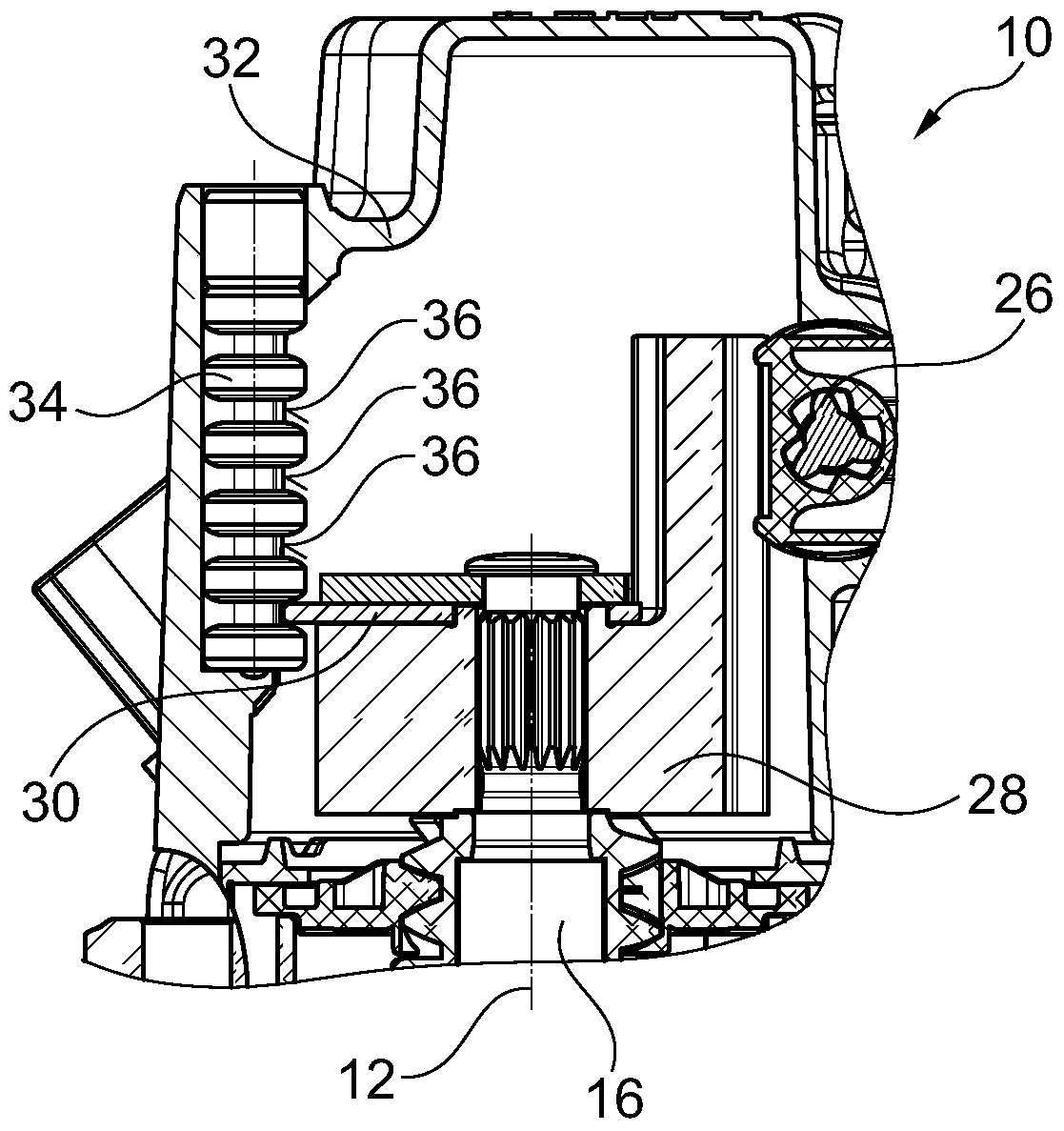
In the actuator assembly 10, according to the active interlocking principle, the chute rod 34 is incorporated as a separate component and therefore requires a certain installation space

Method used


Image

  • actuator assembly
  • actuator assembly
  • actuator assembly

Examples


Embodiment Construction

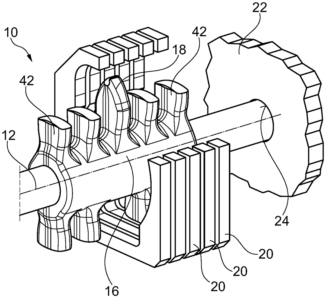
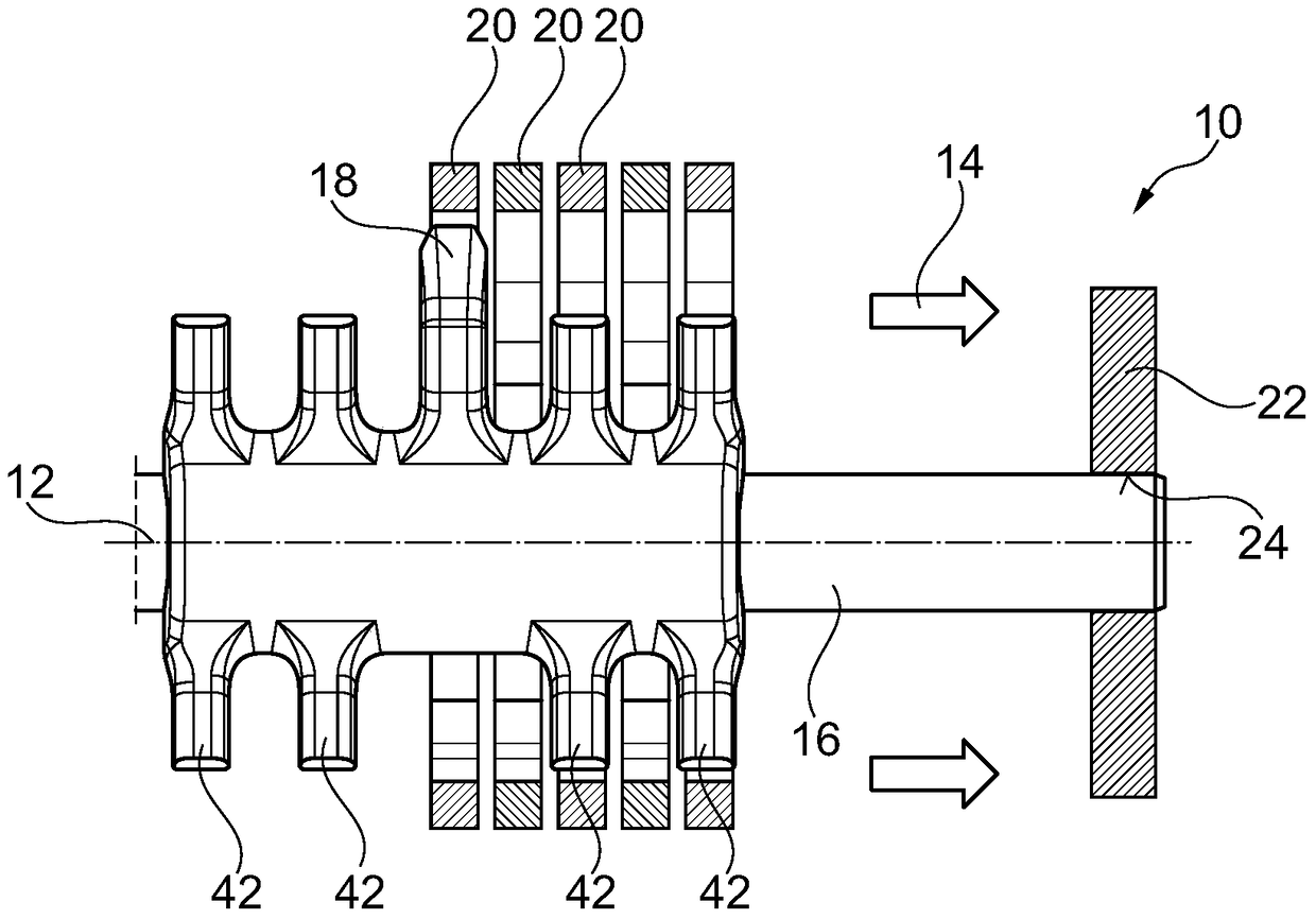
[0023] In the actuator assembly 10 according to the present invention at Figure 4 and Figure 5 In the embodiment shown, with the actuator 10 in the figure 1 , figure 2 and image 3 In contrast to the embodiment shown in , the link guide for the selector shaft 16 is not arranged in the actuator housing 32 , but is formed at the opposite end of the selector shaft 16 by means of a slide bearing 24 superior. In the illustrated embodiment, the convex part of the gate guide is formed by the shift shaft 16 and the recess of the gate guide is formed by the plain bearing 24 , wherein this can also be configured kinematically opposite. For this purpose, the selector shaft 16 has a plurality of radially protruding cams 38 , between which intermediate spaces 40 are formed in each case. The number of intermediate spaces 40 corresponds to the number of shift rails 20 , wherein one cam 38 is provided more than the number of shift rails 20 . The shift finger 18 is spaced significantl...


PUM


Abstract

The invention provides an actuator assembly, in particular for the shifting of gears of a motor vehicle transmission, provided with a rotatable in circumferential direction about a rotation axis and displaceable in the axial direction of control shaft, the control shaft is provided with a protruding finger in the radial direction of shift to shift the gears of the motor vehicle transmission, and one to the shift finger spaced bearings for rotatably and displaceable mounting of the shift shaft, the switching shaft and a sliding bearing form a sliding guide for the authorization of a rotation of the shift shaft in certain defined axial relative positions of the shift finger is formed with the slide bearing for sliding bearing. By using the sliding bearing as part of a sliding guide for the shift shaft, a separately provided sliding bearing can be saved so that an actuator assembly is provided with a small space requirement, particularly within a motor vehicle transmission.

Description

technical field [0001] The invention relates to an actuator assembly by means of which, in particular, transmission gears of a motor vehicle transmission can be shifted. Background technique [0002] known in figure 1 , figure 2 and image 3 Shown in the actuator assembly with the so-called "active interlock (Active Interlock)" (AI), in which there is provided a A selector shaft 16 which moves on 14, from which a selector finger 18 projects for displacing a selector rail 20 . The selector shaft 16 can be mounted at one end in a slide bearing 24 arranged in the transmission housing 22 and can be rotated at its opposite end by an actuating device 26 and moved axially by means of the crown gear. On the end pointing away from the transmission housing 22 , the selector shaft 16 has a gate wheel 28 which can engage in a gate provided in the actuator housing 32 via a radially protruding gate disc 30 Rod 34. The gate lever 34 has recesses 36 which correspond to the spacing of...

Claims


Application Information

Patent Timeline
Patent Type & Authority Patents(China)
IPC IPC(8): F16H63/20F16H63/30
CPCF16H63/20F16H63/22F16H63/36
Inventor U·巴斯蒂安R·维勒克
Owner SCHAEFFLER TECH AG & CO KG
Learn More