A throttling part of a flow regulating valve, a valve sleeve of a flow regulating valve and a flow regulating valve
A technology of flow regulating valve and throttling parts, which is applied in the fields of flow regulating valve sleeves, flow regulating valves, and flow regulating valve throttling parts. It can solve problems such as cavitation, large valve pressure drop, erosion, etc., and prevent damage , the effect of improving the service life
- Summary
- Abstract
- Description
- Claims
- Application Information
AI Technical Summary
Problems solved by technology
Method used
Image
Examples
Embodiment 1
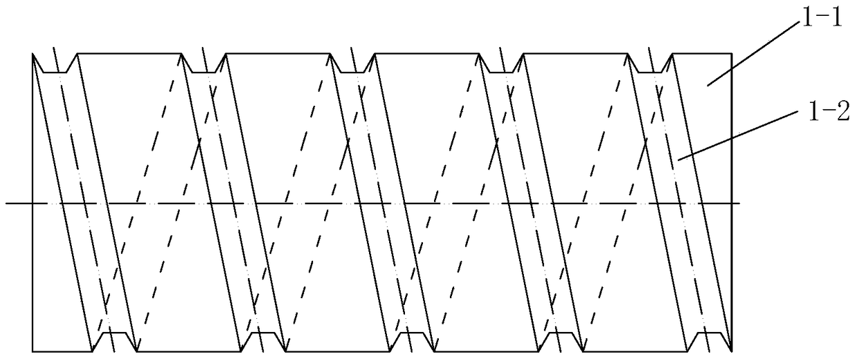
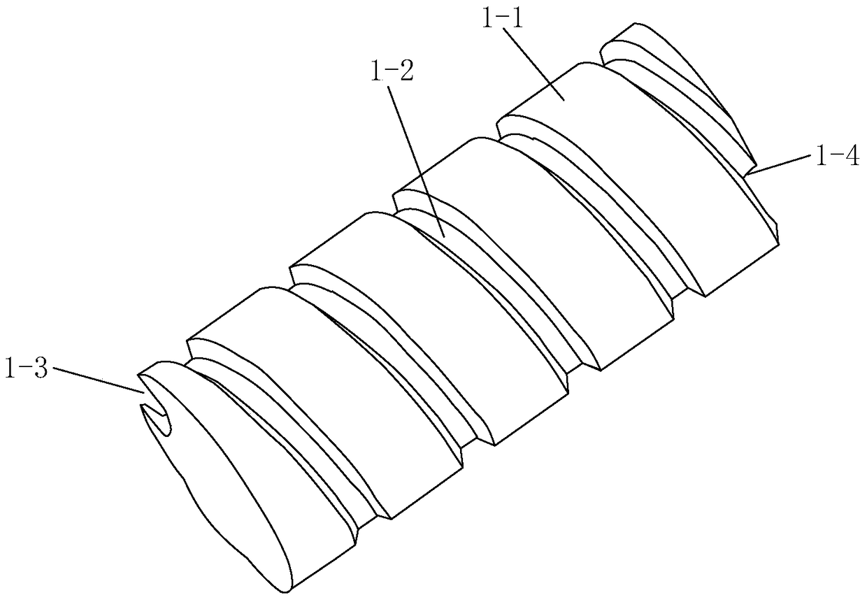
[0040] Such as figure 1 and figure 2 The throttling element of a flow regulating valve shown includes a cylindrical throttling element body 1-1, and the outer wall of the throttling element body 1-1 is provided with a spiral groove 1-2 for reducing the fluid velocity One end surface of the throttle body 1-1 is provided with a fluid inlet 1-3 for the fluid to enter the spiral groove 1-2, and the other end surface of the throttle body 1-1 is provided with a fluid inlet 1-3 for the fluid to enter the spiral groove 1-2. Fluid flows out of the fluid outlet 1-4 of said helical groove 1-2.
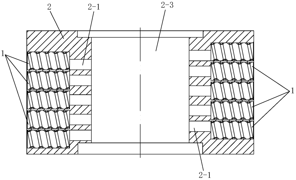
[0041] Such as image 3 The valve sleeve of a flow regulating valve shown includes a throttling sleeve 2 and a plurality of throttling elements 1 described in this embodiment, and a plurality of throttling element installation holes 2 are opened on the side wall of the throttling sleeve 2 -2 and a plurality of communication holes 2-1 for communicating with the throttle member installation hol...
Embodiment 2
[0050] Such as Figure 6 and Figure 7 Shown is a throttling piece of a flow regulating valve, the difference between the throttling piece of the flow regulating valve in this embodiment and the throttling piece of the flow regulating valve in Embodiment 1 lies in: the spiral groove 1-2 It includes a plurality of reaming holes 1-2-1 arranged at intervals along its helical direction and a plurality of recesses connecting two adjacent reaming holes 1-2-1 along the helical direction of the helical groove 1-2. Slot section 1-2-2.
[0051] Such as Figure 8 Shown is a flow regulating valve sleeve, the difference between the flow regulating valve sleeve in this embodiment and the flow regulating valve sleeve in Embodiment 1 is that the flow regulating valve sleeve adopts the The throttling piece 1 mentioned above.
[0052] In this embodiment, the throttling piece 1 is installed in the throttling piece installation hole 2-2 of the valve sleeve of the flow regulating valve when in...
PUM
 Abstract
Description
Claims
Application Information
 - R&D
- Intellectual Property
- Life Sciences
- Materials
- Tech Scout
- Unparalleled Data Quality
- Higher Quality Content
- 60% Fewer Hallucinations
Browse by: Latest US Patents, China's latest patents, Technical Efficacy Thesaurus, Application Domain, Technology Topic, Popular Technical Reports.
© 2025 PatSnap. All rights reserved.Legal|Privacy policy|Modern Slavery Act Transparency Statement|Sitemap|About US| Contact US: help@patsnap.com


