Compressor

A compressor and compression mechanism technology, applied in the field of compressors, can solve problems such as inability to cool the motor, uneven refrigerant gas, etc.

Inactive Publication Date: 2006-07-12
DAIKIN IND LTD
View PDF3 Cites 3 Cited by
  • Summary
  • Abstract
  • Description
  • Claims
  • Application Information

AI Technical Summary

Problems solved by technology

At this time, since the refrigerant gas has the property of flowing in the direction of less resistance, the refrigerant gas does not necessarily flow into the gap uniformly, and the refrigerant gas is uneven in the flow direction of the refrigerant gas.
Therefore, although under the existing structure, the motor can be cooled by refrigerant gas, it cannot be effectively cooled.

Method used


Image

  • Compressor
  • Compressor
  • Compressor

Examples


Embodiment Construction

[0054] Hereinafter, embodiments of the present invention will be described in detail with reference to the drawings. It should be added that the present invention is not limited to the following examples.

[0055] (first embodiment of the present invention)

[0056] The first embodiment of the present invention is applicable to the following compressors. The compressor is a scroll type compressor. This scroll compressor is connected to, for example, a refrigerant circuit (not shown) of a refrigerating apparatus that performs a vapor compression refrigerating cycle, and compresses refrigerant gas.

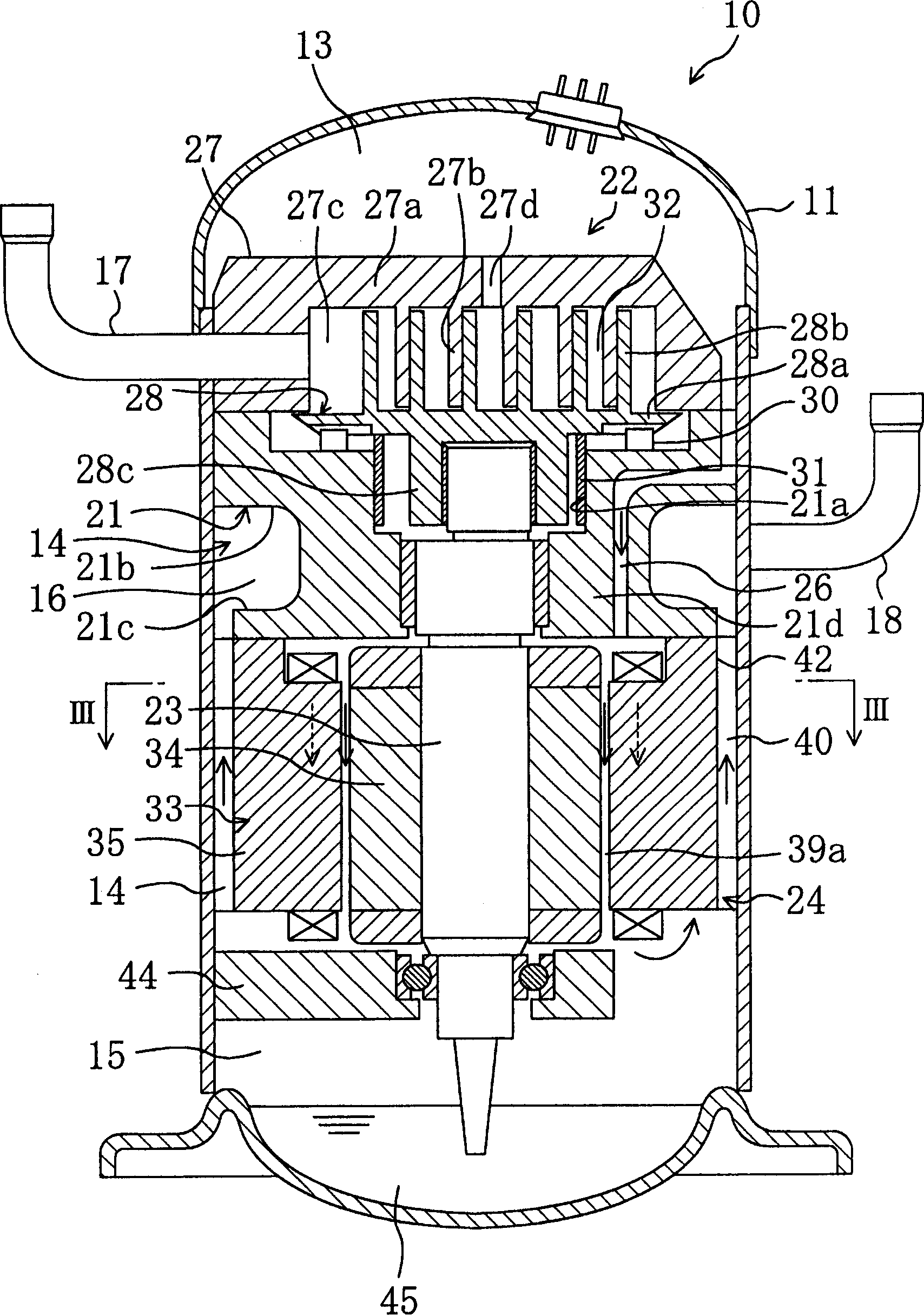
[0057] Such as figure 1 As shown, the compressor 10 involved in this embodiment has a casing 11 composed of a pressure vessel, and the casing 11 is equipped with: a frame 21 as a dividing part fixed on the casing 11, and a frame 21 installed on the casing 11. A scroll compression mechanism 22 at the upper end of the frame 21 and a motor 24 provided with a drive shaft 23 and arra...


PUM


Abstract

A partition member (42) is installed between a frame (21) and the stator (33) of an electric motor (24). The partition member (42) establishes communication between a connection passage (26) and a gap (39a) and between a gas passage (40) and a delivery space (16). The refrigerant gas delivered from a compression mechanism (22) entirely flows into the gap (39a) and passes through a communication space (15) and then flows through the gas passage (40) so as to be delivered from a delivery pipe (18).

Description

technical field [0001] The present invention relates to a compressor, and more particularly to a cooling measure for an electric motor. technical background [0002] Hitherto, as compressors, electric compressors disclosed in Japanese Laid-Open Patent Publication No. Hei 5-164069, JP-A No. 10-22381 or JP-A No. 2-169887 are known. In this electric compressor, a compression mechanism and an electric motor for driving the compression mechanism are housed in a hermetic casing. Such a compressor is connected to, for example, a refrigerant circuit of a refrigeration device or the like, and is used to compress refrigerant gas. In this compressor, the compression mechanism includes: a fixed turbine and a movable turbine, and the fixed turbine is fixed on a housing through a housing; It consists of a rotating rotor and a drive shaft fixed to the rotor. The rotation of the rotor rotates the drive shaft to drive the compression mechanism. On the other hand, a portion of the outer p...

Claims


Application Information

Patent Timeline
Patent Type & Authority Applications(China)
IPC IPC(8): F04B39/06F04C29/12F04C18/02F04C29/00F04C29/04
CPCF04B39/06F04C18/0215F04C29/045F04B39/023F04B35/04F04B39/121F05B2210/12F05B2240/10
Inventor 堀和贵清水孝志
Owner DAIKIN IND LTD
Why Eureka
Try Eureka