Steam generator and steam box with steam generator

A technology of steam generator and steam box, which is applied in the direction of steam generation, steam separation device, steam boiler components, etc. It can solve the problems of excessive condensed water in the inner tank, blockage of steam passage, water splashing, etc., and achieve the purpose of prolonging steam Flow path, condensate reduction effect

Active Publication Date: 2020-06-12
NINGBO FOTILE KITCHEN WARE CO LTD
View PDF6 Cites 3 Cited by
  • Summary
  • Abstract
  • Description
  • Claims
  • Application Information

AI Technical Summary

Problems solved by technology

When the volume of the steam generator is constant and the power is high, the water inside boils more violently, and water splashes in the volume, and finally enters the inner tank, resulting in too much condensed water in the inner tank, which brings some inconvenience to the cleaning of the inner tank
[0003] When the existing steam box is working, the steam discharged from the inner tank gathers in the air deflector of the air exhaust assembly, a part of the wind is discharged through the air deflector, and the other part forms condensed water and flows back through the exhaust port on the air deflector Into the inner tank, not only easy to smell, but also lead to more condensed water in the inner tank
In addition, when the steam valve of the existing steam box fails, the steam passage will be blocked, and the air pressure in the steam generator will rise sharply, posing a safety hazard

Method used


Image

  • Steam generator and steam box with steam generator
  • Steam generator and steam box with steam generator
  • Steam generator and steam box with steam generator

Examples


Embodiment Construction

[0028] The present invention will be further described in detail below in conjunction with the accompanying drawings and embodiments.

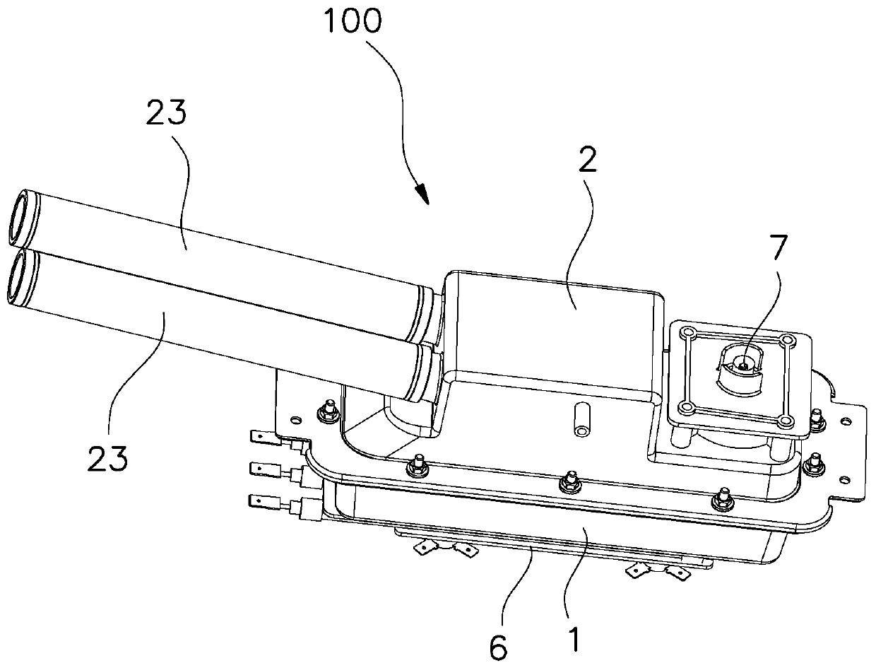
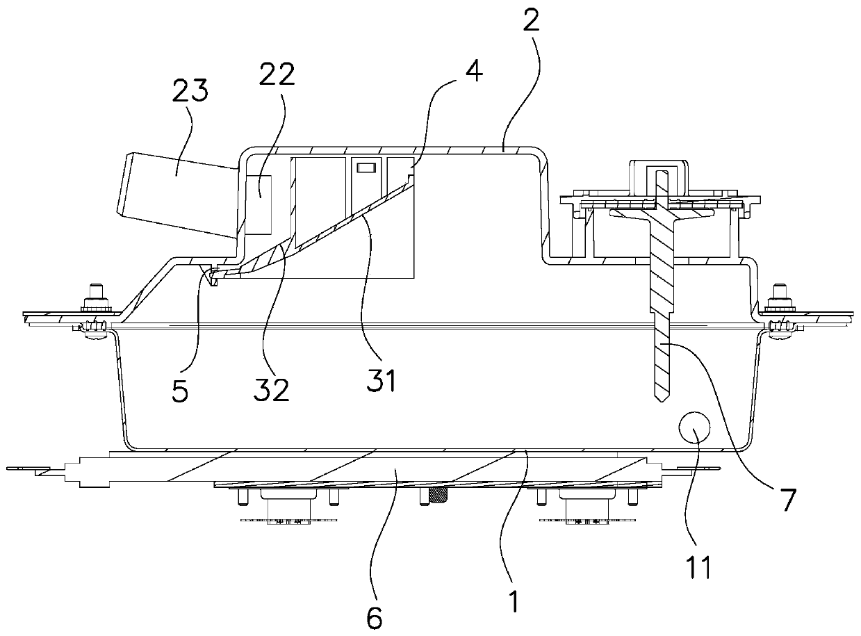
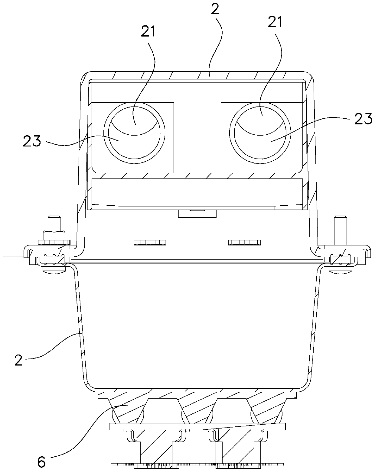
[0029] Such as Figure 1 to Figure 5 As shown, the steam generator 100 in this embodiment includes a base 1, an upper cover 2 and a flow baffle 3, the base 1 is provided with a water inlet 11, the upper cover 2 is provided with an air outlet 21, and the edge of the air outlet 21 has The boss extending inside the upper cover, the boss 22 is a hollow cylindrical boss, the edge of the air outlet 21 has an air outlet pipe 23 extending outside the upper cover, and the air outlet pipe 23 is inclined upward from bottom to top along the air outlet direction, Moreover, the lower edge of the air outlet hole of the air outlet pipe 23 is not lower than the lower edge of the air outlet 21 .

[0030] The baffle 3 is installed inside the upper cover 2, the baffle 3 is close to the air outlet 21 of the upper cover 2, the bottom of the baffle 3 forms a baffle...


PUM


Abstract

A steam generator comprises a base and an upper cover on the base. An air outlet is formed in the upper cover, a flow baffle is installed in the upper cover, the flow baffle is close to the air outlet, and a flow baffle face which tilts towards the air outlet from top to bottom is formed on the bottom of the flow baffle. A steam inlet gap is reserved between the upper portion of the flow baffle and the upper cover, and a water steam backflow gap is reserved between the lower portion of the flow baffle and the upper cover. According to the steam generator, the flow baffle close to the air outlet is arranged in the upper cover, so that the steam generated when water is boiling passes through the tilted flow baffle face first, and then passes through the steam inlet gap between the flow baffle and the upper cover of the steam generator to flow towards the air outlet, and the steam circulating path is prolonged. The flow baffle reduces condensate water flowing towards the air outlet to a certain extent, moreover, due to the water steam backflow gap between the lower portion of the flow baffle and the upper cover and the tilted structure of the flow baffle face of the flow baffle, it isensured that the condensate water accumulated in the flow baffle can flow back into the steam generator, and therefore, the boiling water steam in an evaporator is effectively prevented from enteringan inner container.

Description

technical field [0001] The invention relates to a cooking device with a steaming function, in particular to a steam generator and a steamer equipped with the steam generator. Background technique [0002] The steam generator is one of the essential parts of the existing household appliances with steaming function. Taking the steam box frequently used in the household kitchen as an example, the steam box includes a water tank, a steam generator, a steam heater and a drum. Wind device and other units. Existing steam generators generally include a base and a heating assembly installed on the outer surface of the base. The heating assembly heats the water inside the base to generate steam, and the generated steam flows out of the steam generator and enters the cooking inner tank to affect the food. for heating. The volume of existing steamers on the market is generally lower than 50L. Correspondingly, the power and volume of the steam generators are relatively small. When it ...

Claims


Application Information

Patent Timeline
Patent Type & Authority Applications(China)
IPC IPC(8): F22B37/30F22B37/50F22B37/44A47J27/04
CPCA47J27/04F22B37/30F22B37/44F22B37/50
Inventor 蒋圣伟
Owner NINGBO FOTILE KITCHEN WARE CO LTD
Why Eureka
Try Eureka