Fully Dynamically Balanced Couplings

A coupling and semi-coupling technology, which is applied in the field of high-performance connection transmission of rotating units, can solve problems affecting dynamic balance accuracy, etc., and achieve the effects of improving dynamic balance accuracy, eliminating geometric imbalance factors, and high dynamic balance accuracy

Active Publication Date: 2017-12-12
沈阳申克动力机械有限公司
View PDF7 Cites 0 Cited by
  • Summary
  • Abstract
  • Description
  • Claims
  • Application Information

AI Technical Summary

Problems solved by technology

In addition, the weighted surface is limited during on-site balancing and dynamic balancing, which will also affect the accuracy of dynamic balancing

Method used


Image

  • Fully Dynamically Balanced Couplings
  • Fully Dynamically Balanced Couplings

Examples


Embodiment

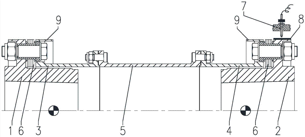
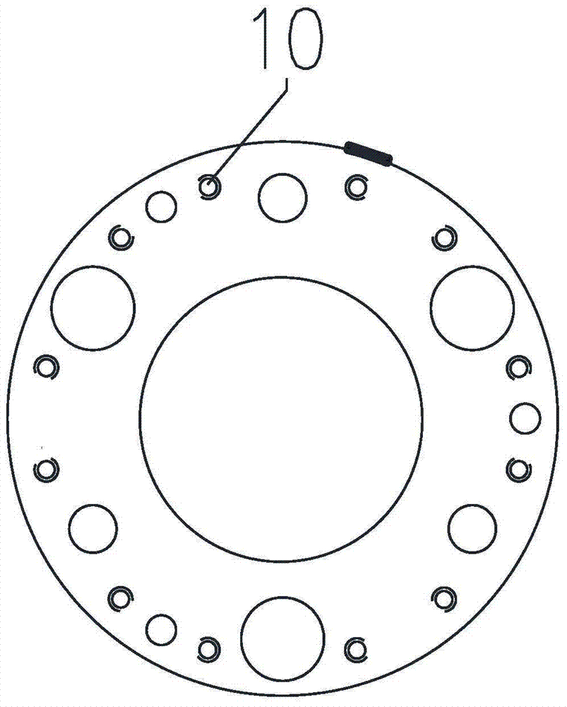
[0022] Such as figure 1 and figure 2 Shown: complete dynamic balance coupling, including power input half coupling 1, power output half coupling 2, input end sheath 3, output end sheath 4, intermediate section 5, diaphragm group 6, Infrared probe 7, key phase magnetic strip 8 and counterweight flange 9. The input end sheath 3 and the output end sheath 4 are set on the shaft hubs of the power input half coupling 1 and the power output half coupling 2 through the counterweight flange 9 respectively, and the power input half coupling The flanges of the coupling 1 and half coupling 2 at the power output end are close to their outer ends, which makes the quality of the coupling close to the supports (bearings) of the machines on both sides to the maximum extent, which is beneficial to improve the shock absorption capacity of the unit. The input sheath 3 is connected to the output sheath 4 through the intermediate section 5 . The diaphragm group 6 is arranged between the input e...


PUM


Abstract

Fully dynamically balanced couplings, including half-couplings at the power input end, half-couplings at the power output end, input end jackets, output end jackets, intermediate sections, diaphragm sets, infrared probes, key phase magnetic strips and accessories Heavy flange; the input end sheath and the output end sheath are respectively set on the shaft hubs of the power input half coupling and the power output half coupling through the counterweight flange; the input end sheath passes through the intermediate section It is connected with the output end sheath; the diaphragm group is set between the input end sheath, the output end sheath and the intermediate section; the key phase magnetic strip is set on the power input end half coupling or the power output end half coupling method on the blue plate; the infrared probe is set on the upper end of the key phase magnetic strip; the counterweight flange is provided with a counterweight screw hole. For the unit equipped with the coupling of the present invention, the key phase magnetic strip, the infrared probe and the shaft vibration detection instrument of the unit itself can be used together to determine the unbalanced mass and phase, and only one stop is required. The screw plug of unbalanced mass is screwed into the heavy screw hole to obtain accurate dynamic balance of the unit.

Description

technical field [0001] The invention relates to a shaft coupling, in particular to a fully dynamic balanced shaft coupling, which belongs to the technical field of high-performance connection transmission of rotating units. Background technique [0002] The rotating unit consists of several rotating machines and couplings, and the rotors and couplings of the rotating machines form the shaft system. Although they are all corrected by precise dynamic balance, the shaft system they form is often unbalanced. In addition, even if the shaft system is balanced, it is often out of balance due to wear of rotating parts, thermal deformation or fouling of flow channels, which affects normal operation. [0003] The current method to solve this problem is to remove the rotor of the unit and transport it to the factory by car for re-balancing correction. The high-end rotor needs to be filled with inert gas, sealed and packaged and transported with soft supports. The cost is high and the ...

Claims


Application Information

Patent Timeline
Patent Type & Authority Patents(China)
IPC IPC(8): G01M1/02F16D3/50
Inventor 林树杰武兵林晓琳于泽谢宇峰乔艳
Owner 沈阳申克动力机械有限公司
Why Eureka
Try Eureka