Detection apparatus of number of layers of PE tube of reeling type irrigation sprinkler

A detection device and sprinkler technology, applied in the direction of optical device exploration, etc., can solve the problems of wrong judgment of PE pipe layers, loss of historical sensing information, low reliability, etc., to achieve direct and effective detection methods and strong anti-interference ability. , the effect of real-time measurement

Active Publication Date: 2015-10-14
JIANGSU UNIV
View PDF7 Cites 6 Cited by
  • Summary
  • Abstract
  • Description
  • Claims
  • Application Information

AI Technical Summary

Problems solved by technology

[0005] 1. The current judgment of the number of PE pipe layers depends on the length of the PE pipe unfolded at the beginning of spraying, which cannot adapt to the change of the initial unfolded length of different PE pipes;
[0006] 2. At present, the reliability of judging the number of PE pipe layers is low. The Hall switches on both sides of the winch support frame will cause errors in judging the number of PE pipe layers due to external interference or unstable detection during the entire operation of the sprinkler; When the system crashes or restarts after a power failure during the entire sprinkler operation process, it is easy to cause the loss of historical sensor information and make the later detection inaccurate

Method used


Image

  • Detection apparatus of number of layers of PE tube of reeling type irrigation sprinkler
  • Detection apparatus of number of layers of PE tube of reeling type irrigation sprinkler
  • Detection apparatus of number of layers of PE tube of reeling type irrigation sprinkler

Examples


Embodiment 1

[0041] The signal emitting device may be an infrared emitting tube, and the signal receiving device may be an infrared receiving tube.

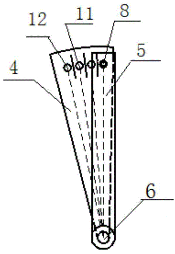
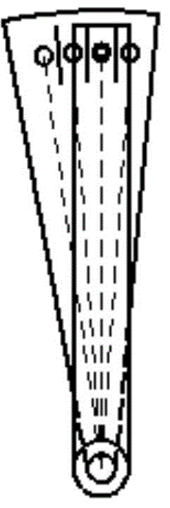
[0042] Such as Figure 2 to Figure 5 As shown, an infrared emission tube F is installed on the static sheet 5 1 8. The moving piece 4 is equipped with four infrared receiving tubes, and the four infrared receiving tubes are in turn infrared receiving tubes A 1 9. Infrared receiving tube A 2 10. Infrared receiving tube A 3 11. Infrared receiving tube A 4 12; the four infrared receiving tubes and the infrared emitting tube F 1 8 have the same radius on the circumference, and the position of the four infrared receiving tubes is opposite to the infrared emitting tube so that the four infrared receiving tubes can receive the infrared signals emitted by the infrared emitting tube. A partition 13 is arranged between the adjacent two infrared receiving tubes to prevent the adjacent infrared receiving tubes from receiving the infrared emitting tu...

Embodiment 2

[0045] The signal transmitting device and the signal receiving device are combined into a pair of photoelectric transceivers.

[0046] Such as Figure 6 to Figure 9 As shown, the moving plate 4 is installed with four pairs of photoelectric transceiver pairs along the circumferential direction, and the four pairs of photoelectric transceiver pairs are photoelectric transceiver pairs D in turn. 1 14. Photoelectric transceiver pair tube D 2 15. Photoelectric transceiver pair tube D 3 16 and photoelectric transceiver pair tube D 4 17. A partition 13 is provided between each pair of photoelectric transceiver pairs to prevent the adjacent photoelectric transceiver pairs from being interfered with each other when transmitting and receiving infrared signals. The transverse width of the static piece 5 can block a pair of photoelectric transceivers, and when the position of the moving piece 4 changes, the static piece 5 can reflect back the infrared signals emitted by the signal emit...

Embodiment 3

[0049] The signal transmitting device and the signal receiving device are combined into a pair of photoelectric transceivers.

[0050] Such as Figure 10 to Figure 13 As shown, two pairs of the photoelectric transceiver pair tubes are sequentially placed in the horizontal direction of the static sheet 5, and the photoelectric transceiver pair tubes are respectively the photoelectric transceiver pair tubes D 5 18 and photoelectric transceiver pair tube D 6 19. When the relative positions of the moving piece 4 and the static piece 5 are P1, P2, P3, and P4 in sequence, the moving piece 4 has a small hole 22 at the positions of P1 and P2 respectively, and the small hole 22 It is the same as the circumference radius of the photoelectric transceiver pair tube. The position of the small hole 22 corresponds to the position of the photoelectric transceiver pair tube. When the photoelectric transceiver pair tube overlaps the small hole 22, the signal emitted by the signal emitting dev...


PUM


Abstract

The invention, which belongs to the technical field of the reeling type irrigation sprinkler, provides a detection apparatus of the number of layers of a PE tube of a reeling type irrigation sprinkler. The detection apparatus comprises a moving plate, a static plate, a signal transmitting device, a signal receiving device, and a signal detection system. The moving plate is installed at one end of an irrigation sprinkler press lever shaft; and a press lever is installed on the press lever shaft. The position of the press lever is changed when the number of layers of a PE tube is changed; and then the moving plate position is changed because of the change of the position of the press lever. The static plate is installed on a rack of the irrigation sprinkler. The signal transmitting device and the signal receiving device are installed on the moving plate or the static plate. The signal receiving device receives different signals to output different codes; and the signal detection system determines the number of layers of the PE tube based on the codes of the signal receiving device. According to the invention, the reliability is high; real-time monitoring and displaying can be realized; and the influence by the historical parameters during the irrigation sprinkler operation process can be avoided.

Description

technical field [0001] The invention belongs to the technical field of reel type sprinkler irrigation machines, and in particular relates to a device for detecting layers of PE pipes of a reel type sprinkler irrigation machine. Background technique [0002] The reel sprinkler irrigation machine is a small and medium-sized irrigation machine with a high degree of automation and low investment per unit area. It is widely used in Northeast and Northwest my country, and its degree of automation has been continuously improved in recent years. In terms of sprinkler irrigation research, scholars at home and abroad have studied the uniformity of reel sprinkler irrigation machines. The Journal of Agricultural Machinery "Water Distribution Characteristics and Experiments of Dual-purpose Sprinkler Irrigation and Hose Irrigation Units" (No. 11, 2009) research The water distribution characteristics and influencing factors of the truss reel sprinkler irrigation with refracting nozzles and...

Claims


Application Information

Patent Timeline
Patent Type & Authority Applications(China)
IPC IPC(8): G01V8/20
Inventor 顾哲袁寿其汤玲迪汤跃陈超
Owner JIANGSU UNIV
Why Eureka
Try Eureka