Terminal pin-inserting device

A pin-in device and pin-in technology are applied in the field of terminal parts processing equipment, which can solve problems such as the inability to meet the requirements of miniaturization and high-density terminal processing.

Inactive Publication Date: 2015-10-14
SUZHOU HANCHUAN CO LTD AKA HARMONTRONICS
View PDF5 Cites 8 Cited by
  • Summary
  • Abstract
  • Description
  • Claims
  • Application Information

AI Technical Summary

Problems solved by technology

Obviously, this traditional method of manually inserting terminals into the workpiece cannot meet the current processing requirements for miniaturized and high-density terminals.

Method used


Image

  • Terminal pin-inserting device
  • Terminal pin-inserting device
  • Terminal pin-inserting device

Examples


Embodiment Construction

[0020] In order to better understand the technical solution of the present invention, a preferred embodiment provided by the present invention will be described in detail below in conjunction with the accompanying drawings.

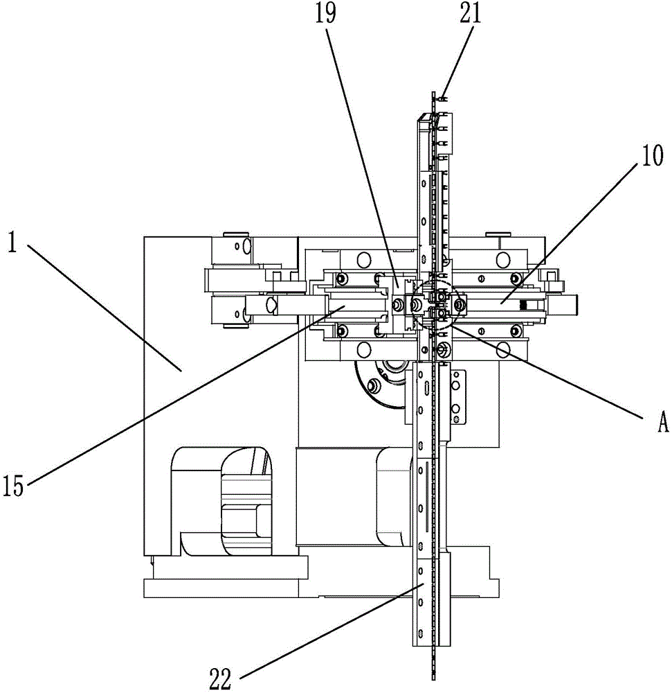
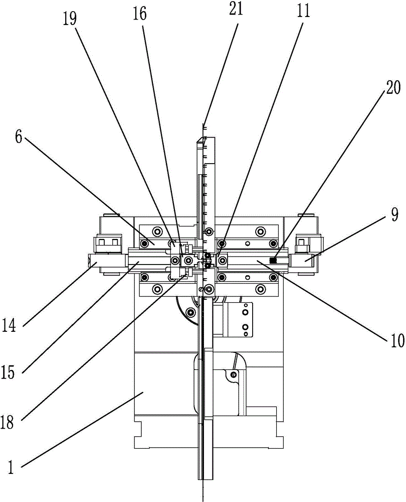
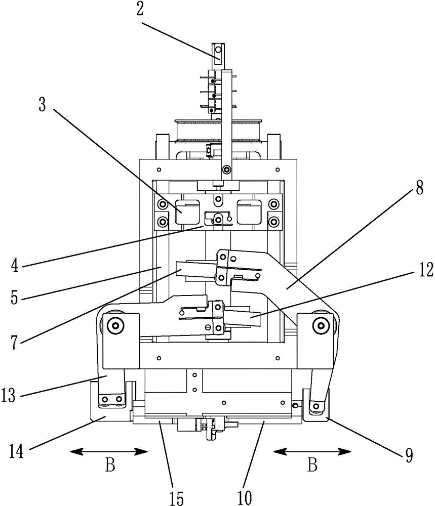
[0021] like Figure 1 to Figure 5 As shown, the terminal pin insertion device of the present invention includes a cam box 1, a cam connecting shaft 2, a pin cam 3, a connecting block 4, a drive shaft 5, a pin pushing block 6, a clamping cam 7, and a clamping swing bar 8. The first U-shaped block 9, the chuck slider 10, the clamping knife 11, the cutting cam 12, the cutting swing lever 13, the second U-shaped block 14, the cutting slider 15, the cutting knife 16, and the static knife Block 17.

[0022] like image 3 As shown, the cam connecting shaft 2 is connected with the cam box body 1, and the pin cam 3, clamping cam 7, and cutting cam 12 are connected with the cam connecting shaft 2. When the driving device drives the cam connecting shaft 2 to run, ...


PUM


Abstract

The invention provides a terminal pin-inserting device which comprises a cam box body, a cam connecting shaft, a pin-inserting cam, a connecting block, a driving shaft, a pin-inserting push block, a clamping cam, a clamping swing rod, a first U-shaped block, a chuck sliding block, a clamping cutter, a cutting cam, a cutting swing rod, a second U-shaped block, a cutting sliding block, a cutting tool and a static cutter block. The terminal pin-inserting device provided in the invention can integrally complete terminal clamping, terminal cutting and terminal pin inserting actions, and has the advantages of high machining precision, fast speed and high production efficiency.

Description

technical field [0001] The invention relates to a processing equipment for terminal parts, in particular to a cam type terminal pin insertion device. Background technique [0002] In the field of terminal parts processing, the traditional method is generally to manually insert terminals into the workpiece. During manual processing, it is easy to cause terminal deformation, missing terminals, and irregular arrangement of inserted terminals, resulting in defective products. With the rapid growth of consumer electronics, automotive electronics, and communication terminal markets, connectors, as an indispensable part of electronic equipment, are also rapidly growing in demand. And because many products have to face smaller and lighter development, there are certain requirements for terminal spacing, appearance size, and height, which put forward higher requirements for the development and application of connectors towards miniaturization and high density. It is obvious that the...

Claims


Application Information

Patent Timeline
Patent Type & Authority Applications(China)
IPC IPC(8): H01R43/20
Inventor 陈雄斌
Owner SUZHOU HANCHUAN CO LTD AKA HARMONTRONICS
Why Eureka
Try Eureka