Welding chuck for welding workstation

A welding work station and welding clamp technology, which is applied in the field of welding clamps and welding clamps for welding work stations, can solve the problems such as the inability of the gun head of the welding clamp to rotate freely, the direct injury of workers to the operating cost, and the low work efficiency of the welding work station. Achieve the effect of low professional technical requirements, compact structure, and improved work accuracy and work efficiency

Active Publication Date: 2015-10-21
YANGZHOU HUALIAN COATING MACHINERY
View PDF5 Cites 5 Cited by
  • Summary
  • Abstract
  • Description
  • Claims
  • Application Information

AI Technical Summary

Problems solved by technology

[0002] At present, for the welding of medium-sized and long conveying pipelines, manual welding is mainly used, and multi-layer operations are inefficient, and the quality is not stable enough. The welding arc and molten steel, the solution is easy to cause direct damage to workers. The operating cost is very high, so in In terms of welding equipment, enterprises urgently need to introduce automatic welding equipment, and welding joints are one of the most critical structures in the entire welding equipment. The welding chucks in the prior art have the following problems; 1) The compatibility of welding chucks is poor, and the application The range is limited; 2) The working efficiency of the welding chuck is low; 3) The gun head of the welding chuck cannot rotate freely, etc. These problems make the work efficiency of the entire welding workstation low, the quality of the product cannot be guaranteed, and the workers are in the process of operation. There are certain security risks in

Method used


Image

  • Welding chuck for welding workstation
  • Welding chuck for welding workstation
  • Welding chuck for welding workstation

Examples


Embodiment 1

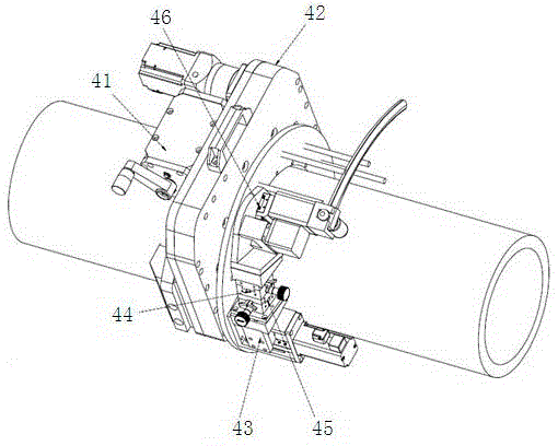
[0023] see figure 1 , a welding chuck for a welding workstation, the welding chuck includes a pipe clamping mechanism 41, an open rotation mechanism 42, a welding torch swing mechanism 43, a manual slide mechanism 44 in the X direction, a manual slide mechanism 45 in the Y direction, and an automatic needle withdrawal mechanism. mechanism 46, the pipe clamping mechanism 41 is fixed on the bottom of the open rotating mechanism 42 by bolts, the welding torch swing mechanism 43 is connected with the C-shaped rotating disk on the open rotating mechanism 42 using bolts, and the Y direction The manual sliding table mechanism 45 is connected with the trapezoidal nut slide block on the welding torch swing mechanism 43, the manual sliding table mechanism 44 in the X direction is connected with the manual sliding table mechanism 45 in the Y direction, and the automatic needle withdrawal mechanism 46 is connected with the manual sliding table mechanism in the X direction. Slide mechanism...

Embodiment 2

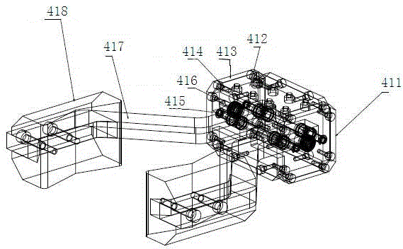
[0025] see figure 1 , figure 2 , image 3 , as an improvement of the present invention, the pipe clamping mechanism 41 includes a bottom plate 411, a cover plate 412, a mounting block 413, a first support pin 414, a second support pin 415, positive and negative trapezoidal screw rods 416, tiles sheet connection plate 417, insulating tile 418, ratchet wrench, the installation block 413 is arranged on the bottom plate 411, and the opening on the installation block 413 is used to install the first support pin 414 and the second support pin 415, the positive The reverse trapezoidal screw rod 416 and the tile connecting plate 417 are provided with corresponding positive and negative trapezoidal threaded holes and support pin holes with clearance fit for sliding, and are used for docking with the support pin shaft and the positive and negative trapezoidal screw rod. The sheet connection plate 417 is fixed between the insulating tile 418 and the bottom plate 411 . The insulating ti...

Embodiment 3

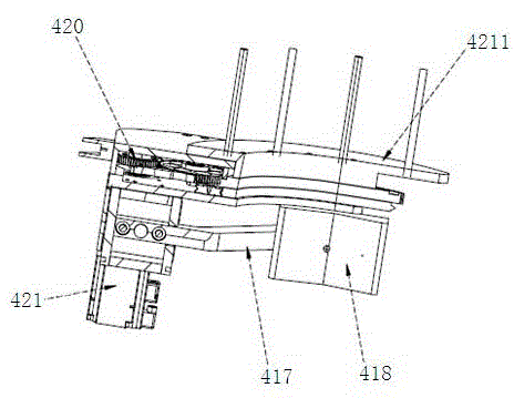
[0027] see figure 1 , figure 2 , Figure 4 , as an improvement of the present invention, the open rotary mechanism 42 includes a servo motor 421, a reducer 422, a reducer mounting plate 423, a mounting base plate 424, a cover plate, a first gear 425, a second gear 426, and a third gear 426 , the fourth gear 428, the fifth gear 429, the C-shaped positioning ring 430, the positioning pin shaft, the bearing, the C-shaped gear 420, the C-shaped rotating disk 4211, the large C-shaped handle 4212, the first gear, the second gear, The third gear, the fourth gear, and the fifth gear are installed on the installation base plate 424, and the installation base plate 424 is provided with a C-shaped positioning groove 4213, and the C-shaped positioning ring 430 is installed in the C-shaped positioning groove 4213. The C-shaped gear 420 is arranged on the C-shaped positioning ring 430, the speed reducer is arranged on the cover plate, and the C-shaped rotating disk is arranged on the C-s...


PUM


Abstract

The invention relates to a welding chuck for a welding workstation. The welding chuck for the welding workstation is characterized by comprising a pipeline clamping mechanism, an open type rotary mechanism, a welding gun swinging mechanism, an X-direction manual sliding table mechanism, a Y-direction manual sliding table mechanism and an automatic needle retreating mechanism, wherein the pipeline clamping mechanism is fixed to the bottom of the open type rotary mechanism; the welding gun swinging mechanism is connected with a C-type rotary disk on the open type rotary mechanism; the Y-direction manual sliding table mechanism is connected with a trapezoidal nut slider on the welding gun swinging mechanism; the X-direction manual sliding table mechanism is connected with the Y-direction manual sliding table mechanism; the automatic needle retreating mechanism is connected with the X-direction manual sliding table mechanism. By means of the technical scheme, the structural design is compact and ingenious; the working efficiency is high; 360-degree free rotation can be achieved; the welding chuck is good in compatibility and wide in application range.

Description

technical field [0001] The invention relates to a welding chuck, in particular to a welding chuck for a welding workstation, belonging to the technical field of welding equipment. Background technique [0002] At present, for the welding of medium-sized and long conveying pipelines, manual welding is mainly used, and multi-layer operations are inefficient, and the quality is not stable enough. The welding arc and molten steel and solution are likely to cause direct damage to workers. The operating cost is high, so in In terms of welding equipment, enterprises urgently need to introduce automatic welding equipment, and welding joints are one of the most critical structures in the entire welding equipment. The welding chucks in the prior art have the following problems; 1) The compatibility of welding chucks is poor, and the application The range is limited; 2) The working efficiency of the welding chuck is low; 3) The torch head of the welding chuck cannot rotate freely, etc...

Claims


Application Information

Patent Timeline
Patent Type & Authority Applications(China)
IPC IPC(8): B23K9/28B23K9/16B23K9/12
CPCB23K9/12B23K9/16B23K9/28B23K9/287B23K2101/06
Inventor 赵凯张辉谭刚
Owner YANGZHOU HUALIAN COATING MACHINERY
Why Eureka
Try Eureka