Connection dismantling robot

A technology of robots and connectors, applied in the field of robots, can solve the problems of high labor intensity, low efficiency, dust entry, etc., to ensure labor safety, reduce labor intensity, and improve work efficiency.

Active Publication Date: 2018-02-23
惊天智能装备股份有限公司
View PDF7 Cites 0 Cited by
  • Summary
  • Abstract
  • Description
  • Claims
  • Application Information

AI Technical Summary

Problems solved by technology

When the equipment is relatively new at the beginning, the pin shaft parts and bolt parts can be easily disassembled, but with the passage of time, the following situations will occur: 1. Between the parts connected by the connecting piece There may be relative movement; 2. The dust in the work will enter the gap between the connecting hole and the connecting piece; 3. The water vapor in the environment will cause the connecting piece and its connected parts to rust; 4. The connecting piece itself may produce Deformation; these situations will make the connecting piece difficult to disassemble, thus hindering the replacement of the connecting piece or the replacement of its connecting parts
[0003] At present, the traditional method of dismantling the connecting parts is to destroy the connecting parts by hitting the connecting parts with a sledgehammer, which not only has a high labor intensity for the workers, but also is inefficient and may cause safety accidents
Another method is to use a punching device. Although the punching device can reduce the labor intensity of workers to a certain extent, it is generally used by hanging on the boom or monorail. This kind of equipment body is separated from the hydraulic station and cannot be flexibly Inconvenient to move, maneuver and use

Method used


Image

  • Connection dismantling robot
  • Connection dismantling robot
  • Connection dismantling robot

Examples


Embodiment Construction

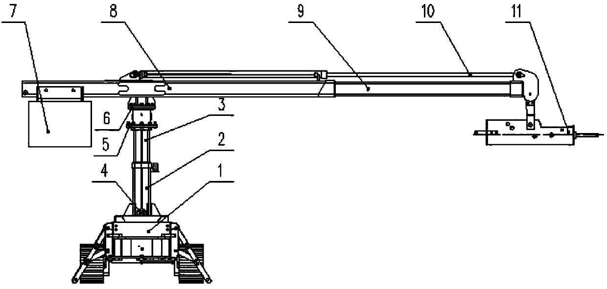
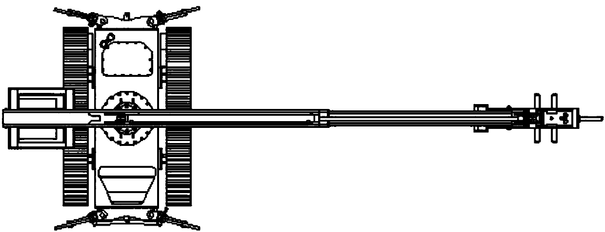
[0015] from figure 1 , figure 2 , image 3 It can be seen that the bolt removal robot device of the present invention includes a walking chassis 1, a lifting mechanism, a telescopic arm mechanism, and a punching body 11. The lifting mechanism is respectively connected with the telescopic arm mechanism and the walking chassis 1 up and down, and the punching body 11 is installed on the telescopic arm mechanism. ; The walking chassis 1 is equipped with four left-right and symmetrical outrigger mechanisms, which are used to support the body or fix the body during work.

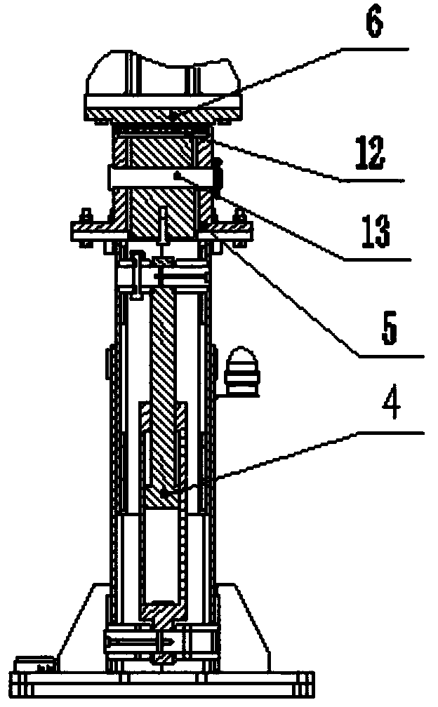
[0016] Wherein, lifting mechanism comprises boom outer arm 2, boom inner arm 3, boom oil cylinder 4; Moving up and down, the boom oil cylinder 4 is arranged inside the boom, and its cylinder end is hinged with the boom outer arm 2, and the rod end is hinged with the boom inner arm 3; the telescopic arm mechanism includes the telescopic boom outer arm 8 and the telescopic boom inner arm 9 1. Telescopic arm oil ...


PUM


Abstract

The invention discloses a robot for dismantling connecting pieces. The robot comprises a travelling chassis, an elevating mechanism, a telescoping arm mechanism, and a punching body, the upper side and the lower side of the elevating mechanism are respectively connected with the telescoping arm mechanism and the travelling chassis, the punching body is arranged on the telescoping arm mechanism, four supporting leg mechanisms in bilateral symmetry are fixedly arranged on the travelling chassis, the elevating mechanism comprises a big arm outer arm, a big arm inner arm, and a big arm oil cylinder, the telescoping arm mechanism comprises a telescoping arm outer arm, a telescoping arm inner arm, and a telescoping arm oil cylinder, the telescoping arm outer arm is connected with the big arm inner arm, the telescoping arm inner arm is arranged in the telescoping arm outer arm and can move left and right, a cylinder end of the telescoping arm oil cylinder is hinged to the telescoping arm outer arm, a rod end of the telescoping arm oil cylinder is hinged to the telescoping arm inner arm, and the punching body is connected to the outer end of the telescoping arm inner arm. According to the robot for dismantling the connecting pieces, the relative position of the connecting piece and an execution mechanism of the robot can be flexibly adjusted via the elevating mechanism, a rotation mechanism, and the telescoping arm mechanism, the connecting pieces can be dismantled, and the work efficiency is improved.

Description

technical field [0001] The invention belongs to the technical field of robots, in particular to a robot used for dismantling connectors. Background technique [0002] Various connecting parts are widely used in the parts that need to be rotated or disassembled in various equipment, such as pin shaft parts, bolt parts, etc. When the equipment is relatively new at the beginning, the pin shaft parts and bolt parts can be easily disassembled, but with the passage of time, the following situations will occur: 1. Between the parts connected by the connecting piece There may be relative movement; 2. The dust in the work will enter the gap between the connecting hole and the connecting piece; 3. The water vapor in the environment will cause the connecting piece and its connected parts to rust; 4. The connecting piece itself may produce Deformation; these situations will make it difficult to disassemble the connecting piece, thereby hindering the replacement of the connecting piece ...

Claims


Application Information

Patent Timeline
Patent Type & Authority Patents(China)
IPC IPC(8): B23P19/027B66F19/00B25J13/00
CPCB23P19/06B25J11/005
Inventor 罗铭孟宪三陈庚邱东峰王涛徐志春徐必勇左立生
Owner 惊天智能装备股份有限公司
Why Eureka
Try Eureka