Supercharge Your Innovation With Domain-Expert AI Agents!

Positioning method and positioning device in optical test

A technology of optical testing and positioning points, which is applied in the direction of testing optical performance, etc., can solve the problems of low positioning efficiency and uncontrollable accuracy, and achieve the effect of high positioning accuracy

Active Publication Date: 2015-10-21
QINGDAO HISENSE MOBILE COMM TECH CO LTD
View PDF9 Cites 10 Cited by
  • Summary
  • Abstract
  • Description
  • Claims
  • Application Information

AI Technical Summary

Problems solved by technology

[0006] The purpose of the present invention is to provide a positioning method and device in optical testing to solve the existing problems of low positioning efficiency and uncontrollable accuracy

Method used


Image

  • Positioning method and positioning device in optical test
  • Positioning method and positioning device in optical test
  • Positioning method and positioning device in optical test

Examples


Embodiment Construction

[0025] The technical solutions provided by the embodiments of the present invention will be described in detail below in conjunction with the accompanying drawings.

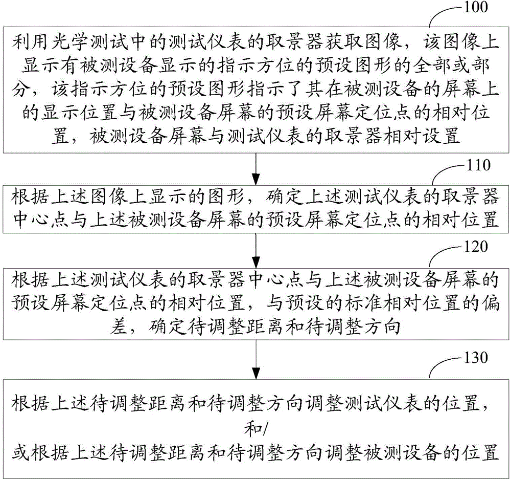
[0026] figure 1 Shown is the flow chart of the positioning method in the optical test provided by the embodiment of the present invention, which specifically includes the following operations:

[0027] Step 100, using the viewfinder of the test instrument in the optical test to acquire an image, on which all or part of the preset graphic indicating the orientation displayed by the device under test is displayed, and the preset graphic indicating the orientation indicates that it is under test The display position on the screen of the device is relative to the preset screen anchor point of the screen of the device under test, and the screen of the device under test is set relative to the viewfinder of the test instrument.

[0028] Specifically, an image acquisition device that shares a viewfinder with the test in...


PUM


Abstract

The invention discloses a positioning method and a positioning device in optical test. The method comprises the following steps: using a viewfinder of a test instrument to acquire an image, wherein all or part of a preset graph of an indicating direction displayed by tested equipment is displayed on the image, the preset graph of the indicating direction indicates where the preset graph of the indicating direction is displayed on the screen of the tested equipment relative to a preset screen positioning point of the screen of the tested equipment, and the screen of the tested equipment and the viewfinder of the test instrument in optical test are oppositely arranged; determining the position of the center point of the viewfinder of the test instrument relative to the preset screen positioning point of the screen of the tested equipment according to the graph displayed on the image, and further determining the adjustment position and the adjustment direction; and adjusting the position of the test instrument according to the adjustment distance and the adjustment direction, and / or adjusting the position of the tested equipment according to the adjustment distance and the adjustment direction. By adopting the technical scheme provided by the embodiments of the invention, the positioning accuracy and efficiency are improved.

Description

technical field [0001] The invention relates to the technical field of optical testing of screens, in particular to a positioning method and device in optical testing. Background technique [0002] In order to ensure the image performance of products, manufacturers of multimedia terminal equipment and display modules must conduct complex optical tests on their products. [0003] Common optical tests include as many as hundreds of test items such as central brightness, color gamut, multi-point uniformity, and viewing angle. Before each test starts, a positioning operation is required, that is, to adjust the relative position between the screen of the device under test and the test instrument. [0004] At present, the equipment under test is fixed on a fixture, and the positioning can only be achieved by repeated observation and adjustment by testers. Specifically, the tester estimates the relative position between the test instrument and the device under test through observ...

Claims


Application Information

Patent Timeline
Patent Type & Authority Applications(China)
IPC IPC(8): G01M11/02
Inventor 王旭明
Owner QINGDAO HISENSE MOBILE COMM TECH CO LTD
Features
  • R&D
  • Intellectual Property
  • Life Sciences
  • Materials
  • Tech Scout
  • Unparalleled Data Quality
  • Higher Quality Content
  • 60% Fewer Hallucinations
Learn More