Continuous zooming non-refrigeration thermal infrared imager

An uncooled infrared and thermal imager technology, applied in the field of infrared thermal imaging, can solve the problems of focal plane shift, image blur, complicated operation, etc., and achieve the effect of improved focusing effect, long working distance, and good image effect.

Active Publication Date: 2015-10-21
HUBEI JIUZHIYANG INFRARED SYST CO LTD
View PDF4 Cites 8 Cited by
  • Summary
  • Abstract
  • Description
  • Claims
  • Application Information

AI Technical Summary

Problems solved by technology

[0005] (1) The relative aperture is small, and the small relative aperture will lead to the decline of the ability of the optical lens to collect infrared heat radiation. When used in conjunction with a lower-sensitivity infrared detector, the image contrast will be significantly worse, the noise will increase, and the image effect will be reduced. poor
[0006] (2) Lack of auto-focus technology. When the target distance changes or the ambient temperature changes, the infrared system will shift the focal plane due to the particularity of its material, and the image will become blurred. At this time, the optical system needs to be adjusted to adapt The focal plane is shifted, and the amount of adjustment is related to the focal length of the lens
The current continuous zoom infrared lens lacks an autofocus module, and often requires manual adjustment. Once zooming, the user needs to adjust the focus, which is cumbersome and inefficient.

Method used


Image

  • Continuous zooming non-refrigeration thermal infrared imager
  • Continuous zooming non-refrigeration thermal infrared imager
  • Continuous zooming non-refrigeration thermal infrared imager

Examples


Embodiment Construction

[0017] In order to make the object, technical solution and advantages of the present invention clearer, the present invention will be further described in detail below in conjunction with the accompanying drawings and embodiments. It should be understood that the specific embodiments described here are only used to explain the present invention, not to limit the present invention.

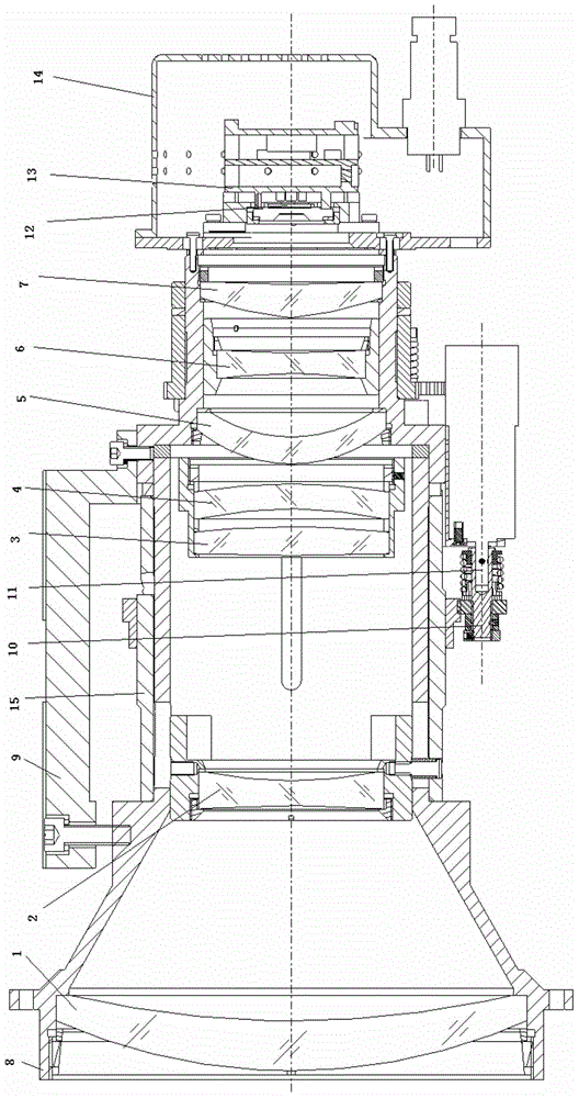
[0018] The invention provides a continuously zooming uncooled infrared thermal imager, such as figure 1 As shown, it includes an infrared detector 12 placed on the image plane of the optical system, a continuous zoom optical system with a large relative aperture, structural components and an autofocus module 13;

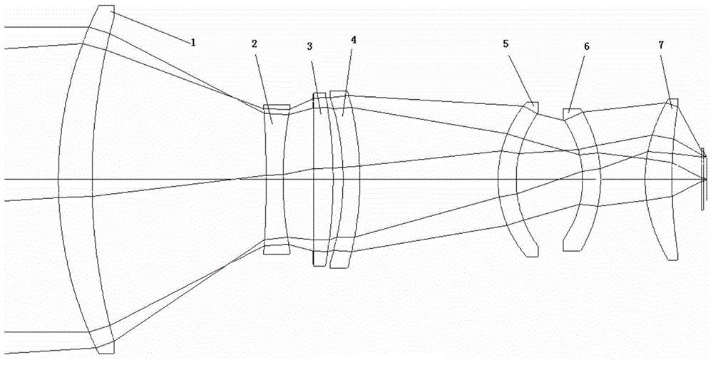
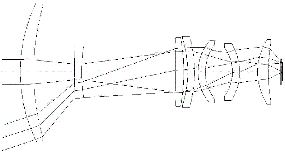
[0019] The relative aperture of the continuous zoom optical system of the present invention is greater than or equal to 1:1. The continuous zoom optical system includes optical lenses arranged in sequence along the optical axis from the object side to the image side, including a front fix...


PUM


Abstract

The invention discloses a continuous zooming non-refrigeration thermal infrared imager, which comprises an infrared detector, a continuous zooming optical system with a large relative aperture, a structural assembly and an automatic focusing module, wherein the relative aperture of the continuous zooming optical system is greater than or equal to 1: 1, and the continuous zooming optical system comprises optical lenses including a front fixed lens, a zooming lens, a compensation lens, a rear fixed lens and a focusing lens which are sequentially arranged from an object space to an image space along an optical axis; the structural assembly comprises a main lens barrel, a zooming cam and a motor, and the main lens barrel is used for fixing the optical lenses in the continuous zooming optical system; the zooming cam drives the zooming lens and the compensation lens to move under the driving of the motor, so as to complete zooming of the optical system; and the automatic focusing module recognizes a defocusing amount and drives the motor to drive the focusing lens through extracting, analyzing and comparing energy values of image edge contours, thereby achieving automatic focusing.

Description

technical field [0001] The invention relates to the field of infrared thermal imaging, in particular to an uncooled continuous zoom infrared thermal imager with a large relative aperture. Background technique [0002] Uncooled infrared products are widely used today. Due to their all-weather day and night observation capabilities, they are widely used in many fields such as monitoring, warning, surveillance, reconnaissance, and forest fire prevention. Compared with cooled infrared products, uncooled infrared thermal imaging cameras do not need to cool the detector, which greatly reduces the cost of components, greatly shortens the start-up time, is convenient to use, and has a wider range of applications. [0003] Continuous zoom uncooled thermal imaging camera, infrared lens with continuous zoom capability, since it can clearly image both far and near targets, it provides users with the most suitable picture and field of view, and is getting more and more popularity in unco...

Claims


Application Information

Patent Timeline
Patent Type & Authority Applications(China)
IPC IPC(8): G02B15/167G02B7/04G02B1/02
CPCG02B1/02G02B7/04G02B15/167
Inventor 郭良贤李勇胡锋雷志雄熊涛马力
Owner HUBEI JIUZHIYANG INFRARED SYST CO LTD
Why Eureka
Try Eureka